|
|
|
|
News The Project Technology RoboSpatium Contribute Subject index Download Responses Games Gadgets Contact <<< pi-top[4] Internet Of Things >>> Physical computingThe videoWarning!GPIO means General Purpose Input Output. Each of that pins can be used to switch a load or to read sensor data. By using GPIOs in a faulty way you can destroy your computer or microcontroller! The circuits shown here are designed with safety in mind but there is no guarantee not to damage your Arduino Uno or Raspberry Pi while using the GPIOs. In this chapter I would like to explain how to switch LEDs, electric motors or servos and how to read signals. Reading sensor data and switching devices by a computer is called physical computing. I am excited whenever a circuit is operating as intended and if objects are "moved by an invisible hand". If you have some experience in soldering work and some base knowledge about semiconductors, this could be an interesting chapter for you.There is a chance to damage your Raspberry Pi or Arduino Uno, to burn your fingers, set power supplies to fire and a lot more while creating your own peripherals from scratch. You know what I am talking about? If not, I recommend buying one of the large number of commercially available expansion boards for the Raspberry or Arduino - there is a higher chance to turn your ideas quickly into reality. Extreme values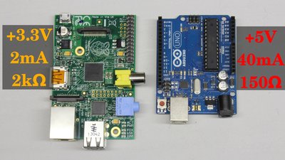
When using the GPIOs you should always have the maximum current and voltage values in mind! The Raspberry Pi uses 3.3V, the Arduino 5V at the pins. Never go above that default voltages! Besides the voltage, the maximum current running through a pin has to be considered! That value should not exceed 40mA at the Arduino and 2mA at the Raspberry. Thus, no load drawing a higher current should get connected to one of the pins because your computer or microcontroller will get destroyed immediately! With Ohm's law we get the minimal resistance of a device drawing that maximum current. We get Maximum current of the Raspberry Pi GPIOsThe GPIOs can deliver a maximum of 16mA per pin with the total current from all pins not exceeding 51mA. When the Pi was designed, they used a figure of 3mA per GPIO pins in determining if the regulator could supply enough current. However, if not all the pins are supplying current then you can divert those pin's share of the current into the ones you are using with no more than 16mA per pin. Hence the total recommended current limit of 17 * 3 = 51mA.Thanks to Alexander for clearing that. However, designing your circuits for a GPIO current of no more than 2 or 3mA keeps you on the safe side! Pins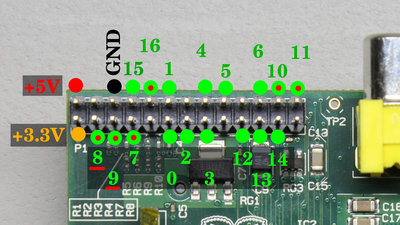
Its good to know what pin belongs to what functionality. There are labels printed on the board of the Arduino, thus the danger of confusion is minimized. You can get the functionality of the Raspberry at the illustration shown here. The numbers of the GPIOs belong to the usage in the software "WiringPi", available at drogon.net as free download. The GPIOs marked by a red dot are turned "on" during boot process. The internal pull-up resistor at GPIO 8 and 9 (approximately 1.5kΩ) can't be disabled by software. 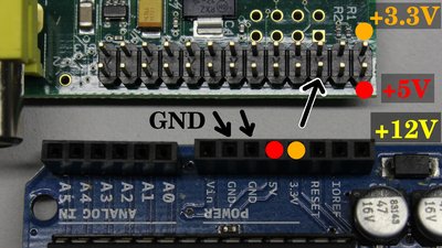
Use black cables for ground, orange cables for +3.3V and red cables for +5V. If an external power supply of 12V is used, the cables should be marked by yellow color. This is the scheme used at computer power supplies. Output mode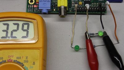
When switched to output mode and turned "off", the potential between ground, which is the negative terminal of the supply voltage, and the pin is (close to) 0V. If the GPIO is turned "on", the potential is 3.3V at the Raspberry Pi and 5V at the Arduino Uno. In the video you can see that the reading at the digital multimiter doesn't meet that specifications exactly - slight variations have always to be considered. One reason is the accuracy of digital multimeters, another one the manufacturing tolerance of the circuits. Furthermore the potential varries with the load connected to a pin. Digital-to-analog converter
With ohmic resistors you can create a 2 channel 8 bit "frequency generator", as demonstrated in my video about the Raspberry Pi. In truth it is a digital-to-analog converter switched at a fast pace. It is a poor quality device (low stability of frequency, no symmetric output signal, maximim frequency just 1kHz), but easy to build. All you need are some resistors with different values. R1 must be twice as high as R2 - exactly, not nearly. For the reasons explained above, they should be clearly above 180Ω at the Arduino respectively 2kΩ at the Raspberry Pi. I have used 100kΩ and 200kΩ resistors. The circuit can be used to demonstrate the functionality of a digital-to-analog converter or to display lissajous figures on an oscilloscope. Switching LEDs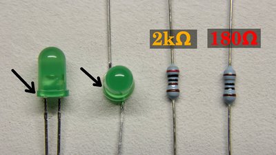
An LED is a simple load for some experiments. You should never connect an LED directly to a pin, because the resistance of that device is very low in operation mode. In order to limit the current, a resistor has to be connected in series to an LED - at least 180 Ohms for the Arduino and 2 Kiloohms for the Raspberry Pi. In the video I am using LEDs with a maximum current of up to 60mA. The disadvantage of this type is the low luminosity when connected to the raspberry Pi. Buy low current LEDs with a higher efficiency. LEDs of type L-934LID have a maximum current of just 2mA and a high luminosity at this low current. Caused by this low current, the series resistor at the Arduino must be at least Furthermore the polarity of an LED has to be considered: To get an LED lighted up, it must be connected with correct polarity to the supply voltage. The negative terminal (cathode) of an LEDs is usually marked by a flat area at the sockets. Furthermore the pin of the positive terminal (anode) is longer than that of the cathode. 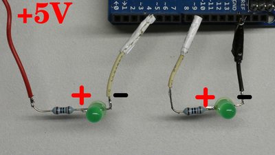
There are two ways of connecting an LED to a GPIO: The first way is to connect the LED resistor combination between the positive terminal an the GPIO (left half of the picture). Use the 3.3V pin at the Raspberry and the 5V pin at the Arduino! The LED is lighted up whenever the GPIO is turned "off". The positive current starts at the positive terminal and runs through the load into the GPIO. it is called "sink current", the pin operates as current sink. The second way is to connect the load between GPIO and ground. The LED is lighted up whenever the GPIO is turned "on". A source current current runs out of the GPIO through the load into the negative terminal. The GPIO operates as current source. Field-effect transistorIn order to control currents above 2mA at the Raspberry Pi respectively 40mA at the Arduino, an amplifying circuit is needed, what field-effect transistors are good for.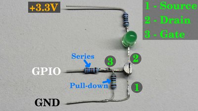
A field-effect transistor has three pins, named source, gate and drain. Have a look at the datasheet of your transistor to find out what pin belongs to what functionality since your circuit won't operate correctly if you swap the pins! In the video I am using n-channel MOSFETs type 2N7000. The source pin of the transistor is connected directly to ground while the drain pin is connected to the positive terminal through the LED and the series resistor. For safety reasons you should use the 3.3V pin for the first experiments. The gate of the transistor has to be connected to the GPIO. That connection can be done directly, but for safety reasons I am using a series resistor to limit the current in case something goes wrong. A second resistor is switched between gate and source of the transistor, operating as pull-down resistor. With this device, the transistor is turned "off" whenever the gate gets disconnected from the GPIO. The series resistor and the pull-down resistor form a voltage divider: The higher the series resistor and the lower the pull-down resistor, the lower the voltage at the gate pin of the field-effect transistor becomes. With a 16kΩ series resistor and a 100kΩ pull-down resistor, we get just If the GPIO is turned "off", thus the potential at the gate is 0V, the resistance of the source-drain line is some megaohms. (Almost) no current runs through the LED, the transistor is turned "off", too. If the GPIO is turned "on", (almost) 3.3V at the Raspberry and 5V at the Arduino are attached to the gate pin of the transistor. The resistance of the source-drain line drops to just some ohms and the LED is lighted up. The transistor is turned "on". 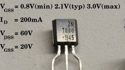
A potential of typically 2.1V is needed to turn the small signal transistor type 2N7000 "on". That potential is called Gate Threshold Voltage (VGSS). Caused by production issues, the threshold voltage can vary between a minimum of 0.8V and a maximum of 3.0V. The 3.3V provided by the Raspberry Pi as well as the 5V of the Arduino are are indeed sufficient to turn the transistor fully "on". Further parameters to be considered are the maximum drain current, listed as 200mA, the maximum drain-source voltage, listed as 60V and the maximum gate-gource voltage, listed as 20V. 
With a transistor circuit, a computer can control a load connected to an external power supply. For example a fan with an operating voltage of 12V can be switched. In order to do this, the negative terminal of the external power supply (e.g. a battery) has to be joined directly with the ground pin of the computer. Don't connect the positive terminal of the battery to the positive terminal of the Arduino or the Raspberry Pi or to any other pin of the computers since the high voltage will inevitably destroy your computing machines! So ensure that it is the negative terminal of the battery that is connected to the ground pin of your computer board! Use black cables for this important line. The drain pin of the transistor is connected indirectly to the positive terminal of the battery through the fan. When turning the pin "on", the fan is running with 12V, spinning with maximum revolution speed. You can use pulse-width modulation to lower that speed. Relay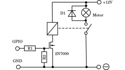
Instead of the fan, the coil of a relay can be controlled via the small signal transistor. Whenever a current runs through that coil, a contact pair attached to the armature is closed by what a load connected to the relay's output circuit is turned on. 12V are a common coil voltage of relays by what a current ranging from 100mA to 200mA runs through the electromagnet of the input circuit. Before connecting the relay to the small signal transistor, have a look at the datasheet or use a multimeter to find out what current runs through the inductor! When switching inductive loads (motor, electromagnet), a diode should be inserted with reverse polarity in parallel to the motor to avoid voltage peaks whenever the load is turned "off". The working principle of that flyback diode is explained in the chapter about pulse-width modulation. 
By cascading relays, currents of more than 100A, thus 1.2kW at 12V operating voltage can be switched by your computer. 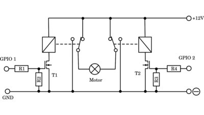
With two relays, each with a changeover switch, an electromechanical H bridge can be built. The motor doesn't turn whenever both GPIOs are turned "on" or both are turned "off". If GPIO is turned "on" whilw GPIO 2 is turned "off", the motor spinns in one direction and whenever only GPIO 2 is turned "on", the motor spins in the opposite direction. T1, T2 = 2N7000, R1, R4 = 16kΩ, R2, R3 = 200kΩ - 1MΩ Power transistor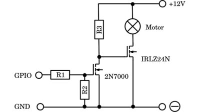
If you want to switch high currents, a power field-effect transistor is needed. Usually the gate threshold voltage of power transistors is 10V and more. Not the Arduino nor the Raspberry Pi have a pin with a voltage above 5V, thus the voltage level must be shifted to 12V by a small signal transistor and an external power supply. If the potential at the GPIO and so at the gate of the small signal transistor (e.g. 2N7000) is 0V, the potential at the gate of the power transistor (e.g. IRLZ24N) is 12V, thus this device is turned "on" and the motor is spinning with maximum power. If the GPIO is turned "on", we get 3.3V respectively 5V at the gate of the small signal transistor. The potential between source and drain of the small signal transistor and so at the gate of the power transistor is 0V, by what that device is turned "off" and the motor stops spinning. The Raspberry as well as the Arduino can switch the motor, but the GPIO has to be turned "on" in order to turn the Motor "off" - the switching behaviour is inverted. Possible values: R1 = 16kΩ, R2 = 1MΩ and R3 = 2kΩ. 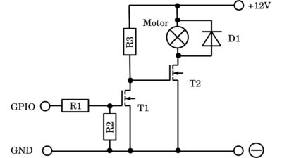
When switching electric motors, a diode should be inserted with reverse polarity in parallel to the motor to avoid voltage peaks whenever the motor is turned "off". The working principle of that flyback diode is explained in the chapter about pulse-width modulation. 
If you intend to use an LED to indicate the switching state of the small signal transistor (which is useful in experimental circuits), you should switch a 10kΩ resistor in parallel to the diode. The resistance of a trainsistor is high, but not infinite when the device is turned "off". The resistance of an LED is low only when a high current runs through this device, thus when the LED is lighted up. If the current is too low to get the LED turned on, the resistance of that special diode is indeed very high. If - as in the video - a multimeter is switched in parallel to the small signal transistor in order to record the voltage drop across that device, the internal resistance of the voltmeter lowers that potential across the transistor clearly. By switching an ohmic resistor in parallel to the LED, the total resistance of LED and R4 is limited to 10kΩ. Thus, a higher voltage across the small signal transistor can be detected. 
A wiper motor is switched by the power transistor. Use a heat sink when swithcing high currents or else the power transistor will fuse during continuous operation! 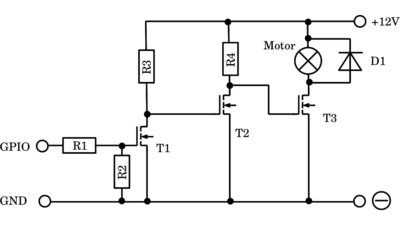
A second small signal transistor is needed if you want to switch the motor synchronously to the GPIO. That additional transistor inverts the signal of the GPIO for a second time, by what the normal switching behaviour is achieved. The motor is turned "on" whenever the GPIO is turned "on" and vice versa. T1 = T2 = 2N7000, T3 = IRLZ24N, R1 = 16kΩ, R2 = 1MΩ, R3 = R4 = 2kΩ Operational amplifier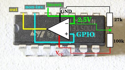
Instead of the small signal transistor, an operational amplifier can be used to amplify the signal of an GPIO. In order to do this, a fixed potential of e.g. 2.5V is attached to the inverting input. The GPIO is connected to the non-inverting input. If the GPIO is turned "off", 0V are applied to the non-inverting input which is lower than the potential at the inverting input, thus the output of the op-amp is on HIGH level, which is the supply voltage (e.g. 12V). The advantage of using an operational amplifier instead of a field-effekt transistor is the adjustable threshold voltage affected only by the voltage divider connected to the inverting input. When using a 100kΩ and a 27kΩ resistor, we get a threshold of 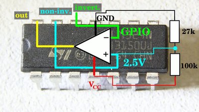
If the fixed voltage is applied to the non-inverting input and the GPIO is connected to the inverting input, the switching behaviour of the op-amp is inverted: The output of the operational amplifier is on HIGH level whenever the GPIO is on LOW level, meaning the computer pin is turned "off". Transistor H bridge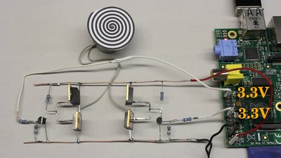
The polarity of the voltage attached to a load can be altered by using transistors instead of relays. Have a look at the chapter about H bridges to learn more about the working principle of those circuits. 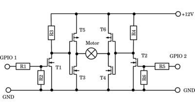
T1 = T2 = 2N7000 T3 = T4 = IRLZ24N T5 = T6 = IRF9Z34N R1 = R5 = 16kΩ R2 = R6 = 200kΩ - 1MΩ R3 = R4 = 2kΩ Digital inputs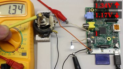
When switched to "input" mode, a GPIO hands a logic "0" to the software whenever the potential at that pin is below a given threshold. A logic "1" is handed to the software if the potential is above a threshold. Usually, the threshold needed to be overrun at rising input voltage in order to trigger a logic "1" is higher than the second threshold needed to be underrun with falling input voltage in order to trigger a logic "0". That behaviour is called hysteresis. The thresholds recorded in the video are 1.34V respectively 1.17V at the Raspberry Pi and 2.49V respectively 2.23V at the Arduino Uno. 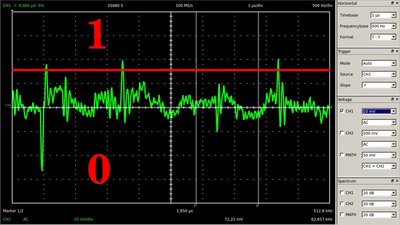
A DC voltage is never ideally constant - there has always ripple to be considered. Without hysteresis, thus if both thresholds are identically and the input voltage is close to that threshold, the input state changes between "0" and "1" even with a tiny interference. 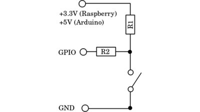
A simple way of attaching the correct voltage to an input pin is using a switch or push button connected to two resistors in a range between 10kΩ and 100kΩ. One terminal of the switch is connected directly to ground of the computer, while the second terminal is connected to both resistors. The second terminal of R1 is connected to +3.3V at the Raspberry respectively +5V at the Arduino. The second terminal of R2 is connected to the input pin. If the switch is "open" there is a potential of (almost) 5V respectively 3.3V across the switch and so at the input pin, thus a logic "1" is detected. If the switch is closed, the reading at the input pin is 0V, thus a logic "0" is detected. The state of the switch can be read by software. R1 is a pull-up resistor, R2 is for safety reasons: If the pin is accidentally switched to output mode and turned "on" while the switch is closed, a high current would run through the pin without that resistor, thus the computer would get destroyed immediately. The resistor limits that current and saves your Raspberry or Arduino. Error free software doesn't exist - so never forget to implement protective resistors! Note that the internal pull-up resistor at GPIO 8 and 9 of the Raspberry Pi can't be disabled by software, thus this circuit layout doesn't work at P1-3 and P1-5! The internal pull-up resistor at those two pins is approximately 1.5kΩ which is why there will be a HIGH signal detected even if the switch is closed! Don't forget to disable the pull-up / pull-down resistor by software when using this circuit layout! Analog inputs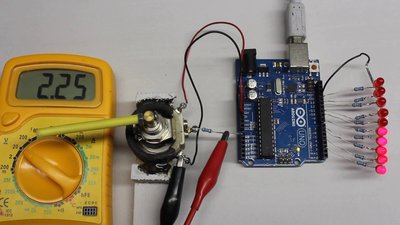
The Arduino has 6 analog input pins. Those pins can be used to read the exact value of a potential instead of merely returning a "0" or "1" if the voltage is above or below a threshold. The potential is returned as an integer value between 0 and 1023 Note that the voltage at an analog input must also be kept below 5V! Simply connect a potentiometer between ground and the +5V pin. The middle pin of the potentiometer is connected to the analog input pin of the Adruino - through a 16 kiloohms resistor for safety reasons. Now, the position of the potentiometer's sliding contact can be detected. Servos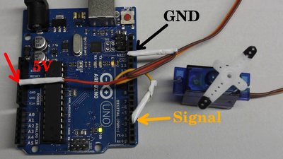
There are thee cables coming out of a servo: Plus, ground and the cable for the control signal. In theory, the 5V pin of the Raspberry Pi or the Arduino can be used to power a servo, but keep in mind that the current drawn by a standard servo exceeds 500mA under load, which is above the maximum current of those pins. A single micro servo can indeed be powered by the 5V pin of the Arduino since the microcontroller allows currents up to 400mA and the current drawn by a micro servo is around 200mA. The black or brown cable is connected to a ground pin of the Arduino, the red cable to the 5V pin. The orange or white cable for the control signal runs to one of the pulse-width pins of the Arduino. Since servos are very common devices, the Arduino as well as the Raspberry Pi provide software routines generating that special pulse-width signal. 
An external supply voltage is needed to power the standard servo connected to the Raspberry Pi. The negative terminal of the battery with a nominal voltage of 6V has to be connected to the ground pin of the computer and that of the servo. The red cable of the servo is connected to the positive terminal of the battery. Eventually a small signal transistor is needed as "level shifter" since some servos need 5V pulses at the signal cable - other types can indeed be controlled by 3.3V pulses. As described above, the pulse-width signal is inverted by the dmall signal transistor, which must be compensated by software. Board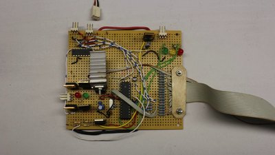
The type of wiring used in the video is clear, but caused by the many blank cables there is a high danger of shorting a circuit. In practice you should solder all devices on a board or use a breadboard for experimental circuits! Don't put a board on a metal plate (e.g. computer housing) or a conductive surface to avoid shorting the circuits! Use kink protections for cabling running to your board. I have spent several hours of my life finding broken cables on experimental boards... At this board you can see a row of 16kΩ resistors at the end of the ribbon cable running to the Raspberry Pi. These series resistors limit the current through the GPIOs in case something goes wrong. Use ribbon cable connectors instead of single cables. Whenever detachable connections are needed, use jacks with a reverse polarity protection. I have damaged several semiconductors with wrong polarity and I guess you will articulate rude words if that happens to you... External power supply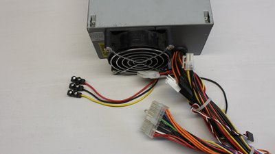
Computer power supplies are usefull whenever high currents are needed to operate a circuit. The black cables are ground, the orange colored cables +3.3V, the red cables +5V and the yellow cables +12V. Join the green cable and ground to turn on the power supply. <<< pi-top[4] Internet Of Things >>> News The Project Technology RoboSpatium Contribute Subject index Archives Download Responses Games Links Gadgets Contact Imprint |
|
|