|
|
|
|
News The Project Technology RoboSpatium Contribute Subject index Download Responses Games Gadgets Contact RelaysThe video about relaysMechanical switch Figure 1:
A switch is an electrical or electromechanical component that can interrupt the current running through an electric circuit. An electromechanical device consists at least of two electrical contacts which can be either in the state "open", meaning the contacts are separated from each other, or in the state "closed", meaning the contacts are touching each other. Ideally the resistance in the state "open" is infinite, while it is zero in the state "closed" and the rise time as well as the fall time while altering the switching state is zero. However there is always a drawback when using real devices: The resistance of a real device in the state "open" is usually very close to an ideal switch, because the resistance of air is around 1016Ωm. The smaller the dimensions of the contacts, the higher the resistance. The power dissipated by a switch when closed depends on its resistance and the current running through the device. Instead of the maximum power, the maximum current is usually listed in the datasheets of switches. Since metals form insulating oxides on their surface in a process called corrosion, the resistance of a closed switch may increase over time. Sometimes the contacts are plated with noble metals to avoid the oxidation of the surface.  Figure 2:
The most simple switch is an on-off switch. The two contacts can be either connected together or disconnected from each other. This type of switch is called single-pole, single-throw (SPST), since one separate circuit can be controlled and one conductive path can be established.  Figure 3:
Two or more switches can be controlled by a single mechanism. The drawing shows a double pole, single throw (DPST) type, since two circuits can be controlled by establishing or braking one conductive path for each circuit.  Figure 4:
Three terminals are required for the most simple kind of a changeover switch. The common terminal (C) is either connected to L1 or L2. This type of switch is named single pole, double throw (SPDT), since one circuit can be controlled by establishing one out of two separate conductive paths. It is sometimes denoted single pole changeover (SPCO). Two or more changeover switches can be controlled by one mechanism. During the changeover procedure, one path is usually interrupted before the other one is closed, which is called break-before-making (BBM) or non-shorting. If both paths are momentarily connected during the switching operation, the device is called make-before-break (MBB) or shorting. 
The common terminal of a single changeover switch can connect to more than just two terminals. The drawing shows a single pole, four throw switch. A state of a switch can be stable or not. A momentary push button switch falls back to a certain state while it is not actuated. The contacts of a push button can either be normally open until closed by operation of the switch ("push-to-make"), or normally closed and opened by the switch action ("push-to-break"). A toggle switch has usually two stable states. When flicked, or toggled, the switch stays in it's position until it is toggled again. Contact bounce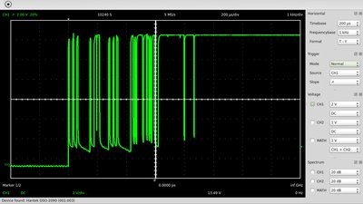
The switch contacts are usually made of springy metals. Caused be the elasticity of the material, the contacts bounce apart several times before making steady contact whenever they strike together. As a result of the contact bounce, a rapidly pulsed current is running through the switch instead of a clean transition from zero to full current. When using mechanical switches in digital circuits, the contact bounce can be misinterpret as multiple switch action. A low-pass filter is often used to eliminate or at least reduce the multiple pulses provoked by mechanical switches. 
A changeover switch in combination with a SR latch can also be used to eliminate the pulses caused by contact bounce. The layout is more complex than a simple low-pass filter, but the gradient of the flip-flops output signal is clearly higher. Arcs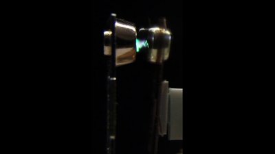
An electric arc is formed as the contacts of a switch open and the power being switched is sufficiently large. The higher the voltage and the smaller the gap between the contacts, the higher the electric field, hence the more air molecules across the gap are ionized and accelerated from one contact to the other. The accelerated ions are capable of cracking more air molecules, thus additional ions are created and the air between the contacts gets heated up by the collisions. The resistance of the so formed plasma is low, hence a current keeps flowing through the switch even while the distance between the contacts is increasing. Not until the gap is large enough the plasma stops existing because of a decreasing electric field between the contact points and so a decreasing number of ions. Even if the spark between the contacts occurs just for a short span of time, the destructive effects caused by the very high temperature of the plasma have to be considered. An arc can also form during closing operation when the contacts approach if the voltage is sufficiently high. Considering the contact bounce, the switch opens multiple times before making a steady contact during closing procedure, which is also causing an arc. Switching a resistor capacitor network in parallel to the contacts, surpresses the formation of sparks. Reed switch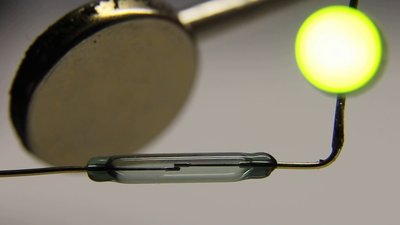
If the contacts are made of ferrous materials, a switch can be operated by an applied magnetic field. A reed switch consists of a pair of magnetizable, flexible metal reeds in a hermetically sealed tubular glass envelope. The contacts may be normally open, closing when a magnetic field is present, or normally closed and opening when a magnetic field is applied. If a permanent magnet is brought near to a normally open switch, the contacts approach and a current flows through the device. If the magnet is removed, the stiffness of the reeds causes them to separate, hence the switch is opened. Since the reed switch is sealed against the environmental atmosphere, the contacts are protected against corrosion and the devices are suitable for use in explosive atmospheres. DC RelayInstead of a permanent magnet, the reed switch can also be actuated by a coil, making it an electrically operated switch, thus a reed relay. Besides a reed switch, other switching mechanisms can also be controlled by coils.
Usually the wire of the coil is wrapped around one leg of a U-shaped core of soft iron, providing a low resistive path for magnetic flux. A movable iron armature with one or more sets of contacts is held in place at the top of the core by a springy, conductive material. While no current is running through the coil, there is an air gap at one end of the armature and the contacts of the relay drawn here are open. There are two electric circuits with complete electrical isolation: One running through the windings of the coil which is named control circuit and the other one running through the load connected to the mechanical switch of the relay, which is named controlled circuit. When an electric DC current is passed through the control circuit, the coil generates a magnetic field that attracts the armature and by the movement of this lever the switch of the controlled circuit is closed. The polarity of the DC voltage applied to the control circuit and so the direction of the current running through the coil doesn't matter. There is always an attracting force generated by the electromagnet. Click so start the animation. When the current to the coil is turned off, the magnetic field is collapsing and the armature returns to it's rest position caused by the force generated by the tension of the spring, thus the switch is opened. AC Relay
The AC power coming out of the wall socket at your home changes direction about 100 times a second. You can see and hear the armature vibrating when operating the coil of a DC relay with a 50Hz AC voltage and if the voltage is high enough, the vibration leads to a making and braking of the relay contacts. The noise caused by the alternating current is known as chattering. A shading coil or shading ring, which is a second coil wrapped around one half of the core material, retains the magnetism when the alternating current becomes zero, by what it is ensured that the contacts do not drop off. As soon as the magnetic flux caused by the alternating current is decreasing, an increasing current is induced inside of the shading ring, which maintains the armature in a magnetized state (see chapter induction for details). 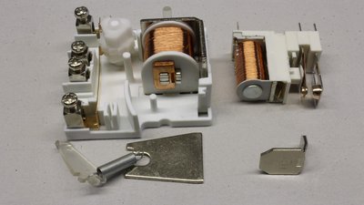
The picture shows the shading ring at the left half of the laminated core with the armature removed to clear the view. If your plan is to operate a DC relay with an alternating current, you can place a rectifier or simply a series diode at the terminals of the coil. Keep in mind that the AC impedance is higher than the wire's DC resistance, hence the coil voltage required to operate the armature is usually higher. Vice versa the coil voltage must be lowered if you are operating an AC relay with a direct current, which can be done without additional wiring like a diode. Electrical propertiesWith an increasing voltage at the terminals of the control circuit, the current through the coil and so the strength of the magnetic force is increasing, too. As soon as the magnetic force overruns the mechanical force caused by the spring, the armature is activated, closing the air gap of the magnetic path. The threshold voltage, required to reliably actuate the controlled circuit is named pull-in voltage, the required current is named pull-in current. When reducing the voltage at the control circuit after the armature was activated, the armature falls back to its rest position as soon as the mechanical force of the spring overruns the magnetic force of the electromagnet. Since the electromagnetic force acting on the armature is higher the smaller the air gap, it is highest while the lever is touching the electromagnet. The hold current and so the minimum voltage required to keep the switch closed (hold voltage) is clearly lower than the pull-in voltage required to operate the armature while the switch is opened. Usually less than half the pull-in voltage is sufficient to keep the state. Common coil voltages are 5VDC, 12VDC, 24VDC, 120VAC and 250VAC.The DC current running through the coil and so the power dissipated by the control circuit depends on the ohmic resistance of the wire. The AC current depends on multiple parameters such as the dimensions of the coil, the core material and so on. In general a low power dissipation is desirable. The switching time is the amount of time from when a relay transitions either from a close to an open state or from an open to a closed state. Usually the time passing by until the open state is reached, differs from the time required to reach the close position since the holding current is lower than the current required to pull-in the armature. Caused by the energy of the collapsing magnetic field, a voltage spike is generated each time the coil of the control circuit is deactivated. If the coil is energized with direct current, a reverse biased diode can be placed in parallel to the device, so that the energy of the induced voltage is dissipated by the current running through the diode whenever the coil gets deenergized. Latching relaysA latching relay, also called impulse, keep or stay relay has two relaxed states, it is bistable. This type of relay has the advantage that its coil only consumes electric energy for the time period the switching state changes. Furthermore the setting of the controlled circuit retains across a power outage.
The picture shows an impulse relay, toggling the state of the controlled circuit with each impulse at the coil of the control circuit using a ratchet and calm mechanism. Click to start the animation. 
When using a core material with a high remanence, there is a magnetization left behind if the magnetic field caused by the coil is removed, hence the armature sticks at the core material even if the current through the coil stops running. To remove the magnetization of the core material, an antipodal field has to be established, hence the polarity of the coil has to be changed. If the voltage applied to the coil and so the current running through its windings is just about sufficient to degauss the core material, the armature is moved to the open position by the spring. The reverse voltage applied to the coil has to be lower than the initial voltage or else the core material is magnetized with reverse polarity, attracting the armature again. 
Another construction principle of a bistable relay is based on a permanent magnet operating as armature. At the animated drawing, the permanent magnet is like a seesaw, at the top of the U-shaped soft iron core. The permanent magnet rests either with its left or right end sticking at the core material. The armature tilts whenever the direction of the magnetic field caused by one of the coils creates a magnetic north pole at that end of the core material, the permanent magnet is currently sticking on. You can either alter the polarity at a single coil or insert two separate coils both being wired to a DC voltage with different polarity. Unknown relay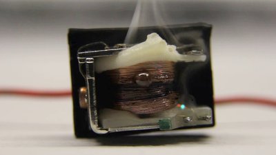
Sometimes it is required to figure out the functionality of a relay's terminals, because there is no datasheet of the accordant type available and the cover can't be removed without destroying the device. Usually the internal wiring scheme is printed somewhere at the relay, but sometimes the labeling is incomprehensible, faded or just missing. Note: You might destroy the unknown device or your power supply when following this instruction! An ohmmeter is required to detect the internal wiring scheme of the relay. Check the resistance between two terminals using all possible combinations. The resistance between two closed switching contacts is zero, so these terminals are easy to detect. The resistance between two terminals internally connected to the relay's coil should be somewhere between some ohm and some kiloohm. To find out the nominal coil voltage, you should connect the detected terminals to a DC voltage source, starting with 3V, then 5V, 6V, 12V and finally 24V. Never ever connect an unknown device to a voltage above 24V! Sometimes a diode is connected in parallel to the coil for the reasons mentioned above. Place a filament lamp (12V, 10W) in series to the coil, to limit the current in case you connect the diode with forward polarity to your voltage source! Change the polarity of the voltage attached to the terminals assumedly connected to a coil before stepping up the voltage, because it might be a bistable type, probably with two separate coils. You can hear and feel the armature bouncing on the core as soon as the threshold voltage is reached. Once you have figured out the threshold coil voltage you can start to detect the functionality of all other unknown terminals, which should be connected to one of the switching contacts. The maximum current ratings of the contacts can't be figured out without going above the limit and so destroying the relay. Simply avoid high currents through the contacts of an unknown relay, especially if it is a tiny device. Circuits
The drawing shows two circuit symbols used for a relay with a single changeover switch. If the coil is deenergized, terminal A and C (common) are joined. 
This is the most simple way of using a relay. The control circuit is operated by a mechanical switch and whenever a current is running through the coil, the relay closes the switch of the controlled circuit. There are several advantages in using a relay instead of operating the load directly by a switch: There is a complete electrical isolation between the control circuit and the power supply of the load. Even a high power load can be controlled by a low power signal or a tiny switch. When replacing the single switch relay by a device with two or more pairs of contacts, several loads can be controlled by one signal. Two thin wires are sufficient to control a high power load over a long distance. 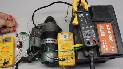
By cascading relays, a high power load can be controlled by a low power signal. Here a tiny push button controls a relay. In turn the relay controls the coil of a soleonid switch. Finally the soleonid switch is used to control the electric starter of a combustion engine. More than 1kW can be controlled by a 1.8W signal when using this circuit. 
When replacing the switch with a transistor, the relay can be operated by electronic signals. 
A relay with a single changeover switch can be used to alter the polarity of the voltage applied to the load, requiring a double supply voltage. 
A single supply voltage is sufficient when using a relay with two changeover switches or alternatively two relays each with a single changeover switch. RS flip-flop
Step 1: By using two relays, both with a single switch, a RS flip-flop can be built. The contacts of relay 1 must be opened in rest position, while those of relay 2 must be closed. At the initial state, the coils of both relays are deenergized. This is one of the two stable states of the circuit with both push buttons in their rest position (open). No current is running through the load. 
Step 2: By pushing the "Set" button, C1 gets energized and a conductive path running through the load is established. Note that the load current is running through the push button during this state of the circuit. Use a relay with two pairs of contacts when switching high power loads! 
As soon as S1 is closed by the relay, an additional conductive path running through the load is established. 
Step 3: When releasing the "Set" button, C1 stays energized by the conductive path running through it's own switch (S1). The state of the circuit is stable with the load connected to the supply voltage. 
Step 4: Pushing the "Reset" button energizes the coil of relay 2... 
...by what S2 is opened, braking the conductive path running through the coil of Relay 1, ... 
...by what S1 falls back to its rest position, braking the path through the load. 
Step 5: Releasing the "Reset" button deenergizes the coil of relay 2 and as soon as S2 falls back to its rest position (closed), the initial state of the circuit (step 1) is reached. 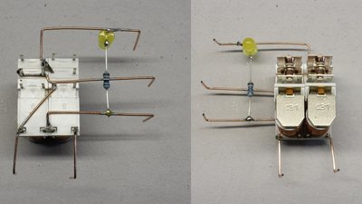
The real circuit shown here is composed of two 12V relays. T flip-flop
Step 1: Another flip-flop composed of two relays, is the toggle flip-flop. Relay number one (C1) has two on off switches, while number two (C2) has two changeover switches. At the initial state, the coils of both relays are deenergized. This is one of the two stable states of the circuit with the push button in its rest position (open). No current is running through the load. 
Step 2: As soon as the button (B1) is pushed, a current is running through the coil of relay 1. 
When the coil of relay 1 is energized, switches 1.1 and 1.2 are closing. A second conductive path (blue) is established inside of the control circuit running through the coil of relay number two. Since the resistance of the newly created path is clearly higher than that of the leg running through the push button, which is ideally zero, (almost) no current is running through C2. 
Step 3: As soon as B1 is released, the conductive path running through that device is broken. The only connection between the positive and negative pole of the supply voltage is running through C1 and C2, which are now switched in series. The voltage drop across C1 equals that across C2. Now, the voltage across C2 must exceed the threshold voltage required to activate the armature, which is why the supply voltage must be twice the nominal coil voltage of the relays. 
As explained above, the hold current is usually clearly lower than the pull-in current. To be able to operate the circuit with less than twice the nominal coil voltage, which can cause damage of the relays during step 2 and step 4, a resistor can be switched in parallel to C1. The lower the resistance value of R1, the lower the voltage drop across C1, but the higher that across C2. The supply voltage should be as close as possible to the nominal coil voltage and the dimension of R1 must meet two conditions: The current through C1 must stay above the hold current and that through C2 must exceed the pull-in current. 
The switches S2.1 and 2.2 change over from 'a' to 'b'. This is the second stable state of the circuit with the push button released. Now half the supply voltage is applied to each energized coil and a current is running through the load connected to S1.2. 
Step 4: As soon as the button is pushed again, a second conductive path running through S2.2 and S2.1 is established. Now, the resistance of the newly established leg is nearly zero, while that through C1 isn't. The total supply voltage is applied to C2 and C1 is deenergized... 
...by what S1.1 and S1.2 are opened. 
As soon as the button is released, the current running through C2 is cut off. When the coil of relay number 2 is deenergized, S2.1 and S2.2 fall back to their rest position, by what the initial state of the circuit will be reached (see step 1). Using an impulse relay (see above) provides the same functionality, but the T flip-flop is the greater challenge to build. There are two main differences: First of all the T flip-flop falls back to the initial state, while the impulse relay retains its state across a power outage. Furthermore no power is required to keep the state of the impulse relay while a current is running through both relays of the T flip-flop when the load is powered during step 3. 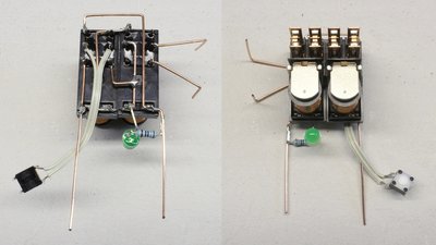
The real circuit shown here is composed of two 12V relays. The leg composed of a 180 Ohm resistor and an LED, being switched in parallel to the coil of relay number 1 makes it possible to operate the toggle flip-flop with a supply voltage of just 12V. Relay clock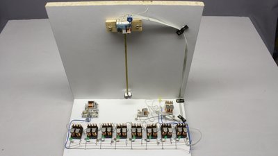
Like explained at the chapter about computing, a counter can be constructed from multiple T flip-flops arranged in a chain. The resulting circuit is a down counter when using positive edge triggered T flip-flops. The circuit is counting the pulses generated by an astable multivibrator. This multivibrator is made of an RS flip-flop being controlled by a third relay with a pendulum at it's armature. The output signal of the RS flip-flop is looped back to the pendulum relay. The result is a clock running in reverse mode. 
Circuit layout of the relay clock: For the astable multivibrator one relay with 2 ON/OFF switches (OFF in rest position), one relay with one ON/OFF switch (ON in rest position) and one relay with one changeover switch is required. Alternatively you can use three relays, each with two changeover switches, so the electrical properties of the devices won't differ. For one T flip-flop, you'll need two relays, each with two changeover switches and one resistor. The LED is optional. News The Project Technology RoboSpatium Contribute Subject index Archives Download Responses Games Links Gadgets Contact Imprint |
|
|