|
|
|
|
News The Project Technology RoboSpatium Contribute Subject index Download Responses Games Gadgets Contact <<< Physical computing Introduction >>> Internet Of Things (IOT)The videoRemote controlAt the previous chapter about Physical computing we have learned how to connect peripherals to GPIOs. This chapter gives you a step by step description of how to control those peripherals through a browser interface. All you need is a second device with an Internet connection.The programming languages used in this chapter are the text based programming languages Perl, C and HTML (HyperText Markup Language). PeripheralsFour types of peripherals are used in this chapter: LEDs, Servos, an H bridge and switches as the simplest type of a sensor.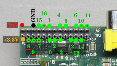
GPIO numbers used at the WiringPi software package available at drogon.net. GPIO 7, 8, 9, 10, 11 and 16 are set to HIGH level during boot process! The internal pull-up resistor at GPIO 8 and 9 can't be disabled by software. 
The LEDs are connected through a 2kΩ serial resistor between GPIO and ground. R1 - R 4 = 2kΩ 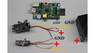
The control lines (usually orange or white cable) of the servos are connected directly to the GPIOs. Ground of the servos (usually brown or black cable) and Raspberry Pi are joined. Plus of the servos (usually red cable) is connected to a 6V battery. Minus of the battery is joined with ground of the Raspberry Pi and the servos. 
An H bridge is used to feed an electric motor with changing polarity. T1, T3 = IRF9Z34N T2, T4 = IRLZ24N T5, T6 = 2N7000 R1, R2 = 100kΩ R3, R4 = 1kΩ R5, R6 = 16kΩ Note that this simple layout of an H bridge is not for high power devices (<200mA)! Have a look at the chapter about H bridges to find improved circuits for higher loads. 
The switches are connected to the GPIOs through 16kΩ resistors (R2 and R4). If the switch is closed while the pin is accidentally set to output mode, the Raspberry Pi won't get damaged. Error free software doesn't exist! The second 16kΩ resistor (R1 and R3) is an external pull-up resistor with one terminal connected to the +3.3V pin of the Raspberry. Note that the internal pull-up resistor at GPIO 8 and 9 can't be disabled by software, thus this circuit layout doesn't work at P1-3 and P1-5! The internal pull-up resistor at those two pins is approximately 1.5kΩ which is why there will be a HIGH signal detected even if the switch at those pins is closed! 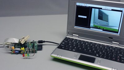
A camera module might be useful to see if your ITO computer works as expected. You can also use an USB camera. In order to make it work, you have to uncomment a line in the script "IOT-Raspberry.pl" (remove the # at the beginning of the line): #system("avconv -f video4linux2... Disable the Raspberry camera module by typing a # at the beginning of the line: system("raspistill -w 320... Warning!The software in this chapter is for doing some experiments around IOT with a Raspberry Pi. It is not for productional use since your traffic runs through my Internet server! Read the whole chapter to see how to set up your own IOT server.Set up the Raspberry PiHow to install Raspbian on a SD card and get started is described at the homepage of the foundation.After that there are two ways of installing my IOT software: Only three command lines: The simple way...Start your Raspberry Pi into terminal mode, login and type:
wget -N http://www.homofaciens.de/download/IOT/InternetOfThings.sh cd DirectoryToSript; sudo ./IOT-Raspberry.pl If you have chosen to start the script named "IOT-Raspberry.pl" automatically, simply reboot your Raspberry Pi and open a brower on a second device, pointing to:http://robospatium.de/IOT/IOT-Status.pl With that automatic reboot enabled, you can remove keyboard, mouse and display from your Raspberry Pi by what you get a very compact Internet Of Things device. You can shutdown the Raspberry Pi through the browser interface before disconnecting it from the power supply. ...and what's behindAdditional software packages are needed for the example code treated in this chapter. Make sure your Raspberry Pi is connected to the internet, open a terminal window (
cd /home/pi Switching GPIOs through CWith the gcc compiler, source code is turned into an executable binary file. The two example codes shown in this chapter can be a starting point for your own experiments around GPIO programming. Lines starting with a double slash "//" are comment lines and not part of the program. Copy the first example into the text editor "Leafpad" (Open a terminal window (
cd /home/pi sudo ./GPIO-pwm& Now the program runs in background and you can control the GPIOs with pulse-width signals. The command line starts with a ">" followed by a space and the directory"/dev/GPIO-pwm/" and creates a file named "GPIO_number-PWM_value". The first part of the file name represents the GPIO number ranging from 0 to 17 and the second one represents the pulse-width signal ranging from 0 to 200, both separated by a "-". This example turns the green LED fully on:> /dev/GPIO-pwm/12-200 The second example turns the yellow LED to half the intensity:> /dev/GPIO-pwm/13-100 Try to switch the red (GPIO 14) and the white (GPIO 0) LED in the same way.Same as the LEDs, servos are controlled by a pulse-width signal. Note that the control signal must have a duty cycle ranging from 5 to 10%, thus the PWM value ranges from 10 to 20! This example turns servo 1 to the center position: > /dev/GPIO-pwm/4-15 With the H bridge, the polarity of the motor can be swapped, thus the direction of rotation can be changed. Additionally the power delivered to the motor is controlled by pulse-width modulation. Note that the direction signal can be either fully on (PWM=200) or fully off (PWM=0)! The example turns the motor with direction "200" and a pulse-width of 70:> /dev/GPIO-pwm/3-200;> /dev/GPIO-pwm/2-70 To observe the state of the two switches, a second program is needed:Copy the source code into "Leafpad" and save the file as "/home/pi/GPIO-status.c". Compile the source with:
cd /home/pi
sudo ./GPIO-status 15
sudo ./GPIO-status 16 Switching GPIOs with Pi-blasterWhen using the above C program to control GPIOs with pulse-width modulation, you might have recognized, that the pulses are not stable, thus you can see the servo lever oscillate around the set point or the LED flicker from time to time. A great way of getting around this problem is using pi-blaster, a program that is also written in C with the source code available for free. Pi-blaster uses DMA channels to create stable PWM signals, which might trouble the graphical mode of the Raspberry Pi, so think twice before using it if you are a beginner! I am not using pi-blaster for the next steps of this tutorial, so you can skip this paragraph. The installing procedure in a terminal window is as follows:
cd /home/pi #define CYCLE_TIME_US 10000 with #define CYCLE_TIME_US 20000 in order to get a signal with a base frequency of 50Hz to drive servos with the accordant pulse-width signal. With pi-blaster you can access the GPIOs through the command line (terminal window). The duty cycle can be varied between 0 and 1. Setting servo 1 to neutral position is done with:
echo "23=0.075" > /dev/pi-blaster
echo "24=0.05" > /dev/pi-blaster
echo "17=0.15" > /dev/pi-blaster
echo "17=0" > /dev/pi-blaster
cd /home/pi/pi-blaster Switching GPIOs from a browser interface with PerlPerl is an interpreted language, thus the source code doesn't have to be compiled to make it run. Internet server typically use Perl to create dynamic content. For the scripts shown here, an additional software package is needed. Type in a terminal:
sudo apt-get update Copy the source code above to "leafpad" and replace the standard password which is in the line: my $password = "TypeYourPassWordHere"; Type a new password between the quotation marks, for example: my $password = "ThisIsMyPersonalPassword"; Note that only alphanumeric characters with no space are allowed for the password. The password must be customized to avoid conflicts with other Raspberry Pis connected through my server, since the password is also used as the ID of your device! Now save the file as "/home/pi/IOT-Rasperry.pl". To make that file executable, open a terminal window and type:
cd /home/pi
sudo ./IOT-Raspberry.pl If your Raspberry Pi is connected to the internet, the script prints the received command data with a terminating "_OK" fom the script "IOT-Command.pl" running on my Internet server:
sudo ./IOT-Raspberry.pl 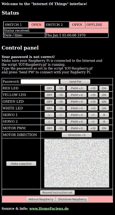
Now you can access your Raspberry Pi and control the peripherals from any other device using the browser interface by pointing at http://robospatium.de/IOT/IOT-Status.pl Type the password you have entered in the script "IOT-Raspberry.pl" and click the button "Send PW". If the password was correct you can switch the GPIOs with the buttons of the control interface. Note that there is a delay of approximately 30s! The status of the switches is updated each 15s or whenever a new command is sent or by clicking on the button "Resend instruction set". Keep in mind that you are connected to your Raspberry through my Internet server! Your Password is stored with weak encryption on my server and I have the encryption key, thus I can also get control of your connected Raspberry Pi by clicking on the buttons of that browser interface whenever I would like to (but I promise not to do so). All other users are locked out by the password protection. Use a password that is not easy to guess, or somebody else might get control of your IOT Raspberry Pi! The pictures taken by your Raspberry are also stored at my server (at least for some minutes)! Of course I could have a look at them, too (but once again I promise not to do so). The camera snapshots are removed from the server by a cron job after a few minutes. Keep in mind that this is just an experimental way of creating an IOT device. The software used is meant to give you an insight of how things could work underneath a colored user interface. If you want to lock me out from your personal Internet Of Things, you have to store two scripts on your Internet server. The first is named IOT-Command.pl: and the second is named IOT-Status.pl Store these two files in a directory on your server and replace "http://robospatium.de/IOT/IOT-Status.pl" with your Internet address in the file "IOT-Status.pl" (4 lines). Make the scripts on your server executable with "chmod u+x *.pl" in a secure shell (ssh) session! The script "IOT-Raspberry.pl" must also be modified to point to your server (replace "http://robospatium.de/IOT/IOT-Status.pl" as well)! UninstallIf you have chosen to start the IOT software automatically during boot process, "IOT-Raspberry.pl" is running in background. That Perl script in turn starts "GPIO-pwm" in background. You can stop both processes with the commands:
sudo killall IOT-Raspberry.pl @reboot root cd /home/pi/InternetOfThings;./IOT-Raspberry.pl You can do this manually with an editor of your choice or with the command:
sudo sed -i '/IOT-Raspberry.pl/d' /etc/crontab Have fun with coding!The programs used in this chapter give you remote access to some base functionalities of the GPIOs. Learn more about programming in C, Perl or HTML to become a computer expert rather than staying on the level of "clicking on colored user interfaces". If you run into trouble with installing, modifying or using my programs, feel free to leave a comment or to contact me by mail. Since my day has just 24h I can't help you fixing more complex projects you have started by your own - sorry!IOT-Raspberry forum threatBesides the comment system on this page, you can leave a post in the threat at the Raspberry Pi forum:http://www.raspberrypi.org/forums/viewtopic.php?f=37&t=98451 <<< Physical computing Introduction >>> News The Project Technology RoboSpatium Contribute Subject index Archives Download Responses Games Links Gadgets Contact Imprint |
|
|