|
|
|
|
News The Project Technology RoboSpatium Contribute Subject index Download Responses Games Gadgets Contact <<< Temperature Oscilloscope >>> Digital multimetersThe video about digital multimetersFunctionsDigital multimeters combine several measurement functions in one unit; typically those instruments are designed to measure resistance, current and voltage.Resistance measurement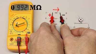
A digital multimeter measures resistance by passing a constant current through the device under test and scaling the indicated voltage drop to the accordant resistance value. The magnitude of the current depends on the dialed measurement range. The higher the range, the lower the current passed through the device under test, because otherwise a high voltage would be required to generate a high current through a high resistive device. Electric energy is needed to do resistance measurement, which is supplied by the internal battery of the multimeter. Which cable is connected to the positive respectively negative terminal of the internal battery, depends on the used multimeter. The resistance of devices like diodes depends on the polarity of the attached voltage and so on the arrangement of the test leads, while it is irrelevant when inspecting ohmic resistors. If set to 2 Kiloohm resistance measurement, the multimeter used in the video can indicate the voltage drop across a forward biased diode. The black test lead has to be connected to the cathode of the diode to be tested and the red test lead to the anode. If the connection is reversed, a single 1 is displayed. A special kind of resistance measurement is the continuity test. If set to this function, the built-in buzzer sounds whenever the resistance is less than 1.5 Kiloohm, hence the measurement can be done without looking at the display. This function is helpful when checking transformers or the windings of an electric motor. Never perform resistance measurements on live circuits! Firstly, the detected value will be corrupt because of the voltages applied to the multimeter and secondly, devices of the circuit or the multimeter could be damaged. Wrong polarity can cause damage of integrated circuits (e.g. op-amps, microcontrollers)! If set to resistance measurement, the multimeter is also named ohmmeter. Voltage measurement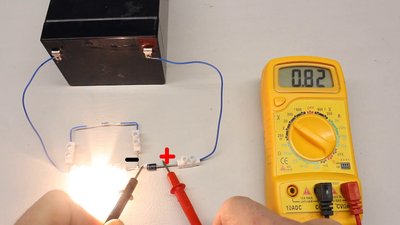
When using a multimeter with the rotary switch set to voltage measurement, the device is also named voltmeter. Voltage is always measured between two points in a system. Usually a common reference potential such as the ground of the system is used as one of the points and the black test lead is connected to that point. The difference in potential between the reference point and the potential at the tip of the red test lead is indicated by the multimeter. When doing voltage measurements, you have to know weather it is DC or AC voltage. The arrangement of the test leads matters when recording DC voltages. The displayed value of the multimeter is negative whenever the red test lead is connected to the lower potential (negative terminal). Usually the black test lead is connected to the negative terminal and the red test lead is used to indicate the difference in potential at several points on a board or in an electric circuit. A difference in potential can not only be detected at a voltage source but also across a device in an electric circuit. To do so, the multimeter has to be connected in parallel to the device under test. Current measurement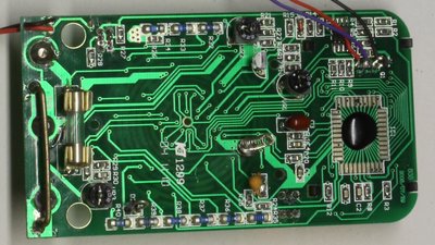
When using a multimeter with the rotary switch set to current measurement, the device is also named Ammeter. In principle the current measurement is a voltage measurement. The current passes a resistor of accurately known resistance and the detected voltage drop across the device is scaled to the accordant current value. The higher the current, the lower the sensing resistance must become, since the resistor in return affects the measurement, as we will se some later. For measurements above 200mA there is a wire strap placed between the middle and the left jack of the multimeter. That special low resistance path is named shunt resistor. The construction allows the current to bypass the tiny contacts of the rotary switch. Those thin strip conductors would not withstand currents above one ampere. 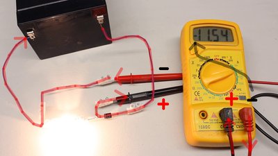
To be able to measure currents, the multimeter has to be switched in series to the device or circuit to be discovered. The circuit must be opened to insert the multimeter. Same as for resistance und voltage measurements, the detection of a current should start with the highest range possible. Thus the rotary switch has to be set to the 10A range and the red test lead must be connected to the left jack to enable the high current shunt. If the detected current is lower than 200mA, you can step down to a lower range. In order to enable the lower range, the circuit under test has to be removed from the voltage source, the red test lead has to be reinserted in the right jack and the rotary switch has to be set to the 200mA range. When doing current measurements, you should disconnect the circuit under test from the power supply before turning the rotary switch. During switchover procedure the current running through the rotary switch of the multimeter is interrupted for a short span of time which can cause high voltage peaks across the switching contacts if inductors are placed in the circuit under test. Caution!What might go wrong, will go wrong! Some things to be considered when operating a digital multimeter:
1.) Voltages over 50V can usually cause dangerous amounts of current to flow through a human being touching not insulated cables of a circuit! Voltage multipliers or inductive devices (electric motors, inductors) can cause dangerous voltages even if the circuit is connected to a power source with less than 50V! 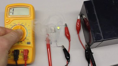
2.) Switch the range selector to the accordant function (voltage, current or resistance) BEFORE connecting the multimeter to the circuit under test. Devices of the test circuit or the multimeter can be destroyed while changing the function with the multimeter connected. While switched to resistance measurement, the multimeter connects the test leads to an internal voltage source. See the description above for details. 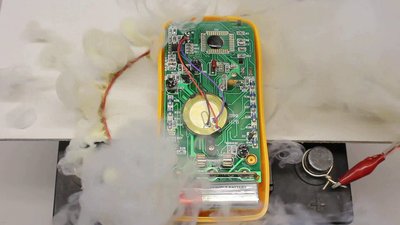
3.) While switched to current measurement, the internal resistance of a multimeter is very low, hence there is danger of shortening the circuit under test! Whenever the high current shunt is enabled (the red test lead is connected to the 10A jack), the multimeter is not fused against high currents! 4.) If the value to be measured is unknown beforehand, set the range switch to the highest range position and step down until the best resolution is obtained. Internal resistanceTo enable voltage detection, the analog-to-digital converter of a digital multimeter has to be connected in parallel to the circuit or device under test by what a current runs through that measuring instrument. The magnitude of the current depends on the voltage drop across the multimeter and the internal resistance of the analog-to-digital converter. The lower the internal resistance of a multimeter, the higher the (undesirable) current running through the instrument, thus the internal resistance of the multimeter must be high when set to voltmeter functionality.When doing current measurements, the multimeter is connected in series to the circuit or device under test. The current passes a resistor of accurately known resistance and the detected voltage drop across the device is scaled to the accordant current value. The internal resistance must be low at the ammeter functionality. While switching one multimeter to resistance measurement, and the second one, which is the multimeter under test, to voltage respectively current measurement, we can determine the internal resistance of the second multimeter directly. In the video, the following values were recorded:
By using three multimeters, the internal resistance of the multimeter under test can be determined by measuring the voltage drop and the current running through the device. The results of the test series recorded in the video is listed in the table below:
The internal resistance while set to DC voltage function is around 1MΩ, hence a current of 0.001mA per volt is running through the measuring instrument. When determining the voltage drop across highly resistive devices with a multimeter, the circuit under test is always affected by the current running through the instrument: 
The circuit drawn here is composed of a voltage divider and a battery: UBat = 12V R1 = 1MΩ R2 = 220kΩ For the voltage drop across the two resistors there is:  and For U2 we get equation (1):  With a battery voltage of 12V we get 2.16V across R2 and 9.84V across R1. To be able to determine the voltage drop across R1, the multimeter has to be switched in parallel to this device. The type of multimeter used in the video has an internal resistance of 1MΩ when set to voltage measurement, by what we get an equivalent circuit: 
The total resistance of R1 and RV is calculated by using [3.12]:  We get 500kΩ for RX and by inserting this value into equation (1) we get a voltage drop of 3.67V across R2 and so just 8.33V across RX. While switching the multimeter in parallel to the upper resistor, the total resistance of R2 (220kΩ) and the multimeter (1MΩ) is 180kΩ. The detected voltage drop across R2 is just 1.83V. According to the measurement, the total voltage of U1 + U2 is just 10.16V, which is 1.84V below the voltage output of the battery. The circuit under test is manipulated clearly by the measurement! A similar problem occurs when doing current measurements: 
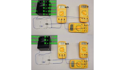
Supply voltage: 3.3V R1 = 180Ω R2 = 100Ω R3 = 2kΩ The current running through R1 is higher the lower the resistance of R1 in relation to that of R2:  The total resistance of R1 and R2 is 64Ω, by what we get a voltage drop of 0.10V across R1 and R2 using equation (1). For the current through R1 we get AccuracyAs explained in the chapter about observational errors, the error limits of measurement instruments have always to be considered. For the multimeters used in the video we get: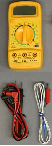 Figure 12:
The given accuracy is as follows: The relative deviation of the displayed value has to be calculated firstly. If the 20V range of DC voltage measurement is selected and a voltage of 10.00V can be read, the relative error is If 10V are displayed while using the 600V range, the lowest decimal place corresponds to 1V. One digit equals 1V, hence we have to consider a deviation of up to 2V. The total deviation is Temperature measurement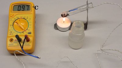
As explained in the previous chapter, a thermocouple is used to measure temperatures. Once again a voltage is detected and scaled into the accordant temperature value. Water with some ice has a temperature of 0°C while the temperature of boiling water is 100°C, however that value depends on the atmospheric pressure. You can use these two points to calibrate your temperature sensor. According to the instruction manual, the multimeter used in the video is capable of detecting temperatures ranging from -20 to +1000°C. Purchase advice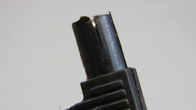
If you intend to buy a digital multimeter, watch out for instruments with a good build quality. The intention of the videos was to analyze the electric properties of low-budget devices. While the accuracy is acceptable, I noticed a very poor mechanical quality of the instruments: To be able to replace the battery, two screws with a plastics thread have to be loosened and the whole rear cover plate has to be removed. After a few replacements, the threads are ruined and the cover can't be closed properly. Furthermore, the insulation of the jacks cracked during usage. Both defects concern the insulation of the multimeter and there is danger to life while measuring high voltages! The cables are very brittle which is why one of them cracked inside of the test probe, resulting in odd readings of the multimeter. This can become very dangerous if you rely on the reading of your multimeter, assuming that an unknown circuit is not attached to a voltage source, but you simply couldn't detect it. The rotary switch of one device doesn't always snap in place correctly, causing wrong readings. So it is a very good idea to spend some more money and buy an instrument of good build quality. You always get what you pay for. For hobbyists the accuracy even of low budget multimeters is sufficient so that's a minor issue to be considered. What kind of functionality your multimeter should provide besides resistance, voltage and current measurement is up to you. <<< Temperature Oscilloscope >>> News The Project Technology RoboSpatium Contribute Subject index Archives Download Responses Games Links Gadgets Contact Imprint |
|||||||||||||||||||||||||||||||||||||||||||||||||||||||||||||||||||||||||||||||||||||||||||||||||||||||||||||||||||||||||||||||||||||||||||||||||||||||||||||||
|
|