|
|
|
|
News The Project Technology RoboSpatium Contribute Subject index Download Responses Games Gadgets Contact Plotter / Printer / Milling machineGeneralAt this chapter I would like to give you a look at the milling machine, I have created about 20 years ago. I used it to manufacture parts of radio controlled model air planes once ago. The milling machine was controlled by a 486 Intel processor (4MB of RAM and for sure less than 1GB disc, it's scraped meanwhile). When I created the video about the Wondermedia Laptop, I removed the dust and did some coding to be able to use it with the new USB interface. The milling machine was replaced by a pen to do some plots. The Z-axis was now simply actuated by a servo. The Raspberry Pi was the next video about cheap, interesting computer systems and to be able to show something new, I replaced the pen by a tiny pump. The source code was enhanced and adapted to the GPIO interface. Now the mechanics can also be used as printer. The milling machine was used to create a case for the Raspberry Pi.The accuracy of the mechanics is poor while compared to commercially available products, but great while compared to the buckled lines I am bringing to paper while painting manually, using my hands. The advantage is that it is easy to build - almost all components are available in do-it-yourself stores. The naked mechanics makes it easy to understand how things work, which is the intention of these pages. The software is written in C. The source code is available at the download section, but remember: It is very experimental! There is no graphical interface. The only supported file formats are Scalable Vector Graphics (*.svg, plotter, milling machine) and 24bit Bitmap (*.bmp, printer). Click to enlarge the pictures - I guess the full view will answer most of your questions. Electronics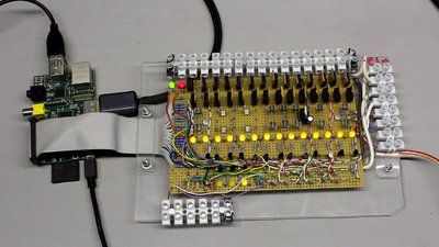
The I/O board of the Raspberry Pi actuates the stepper motors, the servo or the pump. While operating at 12V, 300mA are running through a single inductor of the stepper motors. Mechanics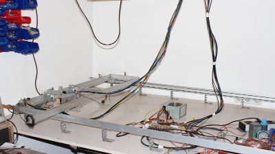
The dimensions of the mechanics are large. I must have had a 1:1 scaled Airbus A380 in mind when I created it. I suggest to build a small one, at least this will enhance the accuracy. The tracks of the X- and Y-axis are made of aluminum bars. The thicker the material, the less it is twisting while operating. 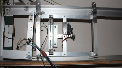
The carriage of the Y-axis is rolling on 4 plastic rolls. 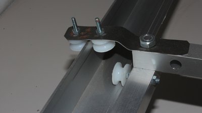
4 additional rolls are guiding the carriage to avoid clearance around the X-axis respectively twisting. 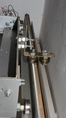
Same goes for the carriage of the X-axis, but steel ball bearings are used instead of plastic rolls (more expensive but more precise). 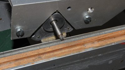
The drive is made of stepper motors. The tip of a T10 torx wrench is running on a M6 thread bar. Other combinations will also work together for the drive. Gear wheels and gear rods are more expensive. 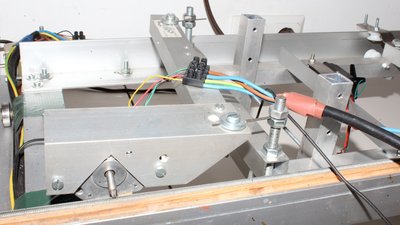
The stepper motors are fixed at the carriage flexibly (flat springs at the two mount points). Whenever the mechanism is jamming, the torx is slipping over the treaded bar, avoiding damage of the drives. 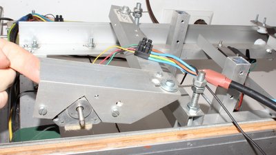
Two motors are actuating the X carriage, only one the Y carriage. 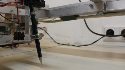
While operating as plotter, the pen is moved up/down by a servo. 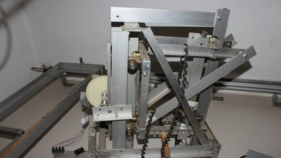
The Y-axis carriage of the milling machine is more complex. The mechanics for the Z-axis is included. 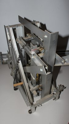
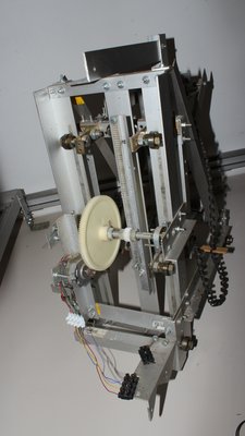
The Z-axis is actuated by a single stepper motor using geared wheels and a gear rod. A disadvantage of the mechanics is, that the milling machine falls down if the stepper motor is turned off, what cost me some 1mm drills... PrinterThe central device of the printer is a tiny pump, driven by a tiny relais. The whole system works, but not very reliable. The quality of the dots is poor (many sattelite drops, different diameters, sometimes missing). It is funny to see it printing, but without optimization it is just for demonstation purposes. The ink I used at the video was from a stylograph, based on water. I also tried ink of a refilling pack of my printer, but the surface tension was propably too low. The fluid was dripping out of the pump as soon as I filled the tank (resulting in a huge contamination of my "printer"). Maybe if there is a way to make a smaller punch at the lower tape (nozzle), this kind of ink will also be suitable. Because of the hydrostatic pressure, that also happened with the water based ink at a too high fluid level inside of the tank.
The pump of the printer is actuated by a tiny 12V relais. The lever is hammering on the top foil if a voltage is attached to the inductor. By turning the screw at the top of the relais, the stroke of the lever can be adjusted. 
The diameter of the big hole at the top plate is 10mm. It is covered by an adhesive tape. Inside of the ink tank, a 2mm hole is drilled. A flute between the two holes is running at the bottom side of the top plate. 
A 2mm hole is drilled in the bottom plate. Those hole is also covered by an adhesive tape. A tiny hole in the middle of the tape is punched by a very pointy needle, operating as the nozzle. The bottom plate covers the 2mm hole and the flute of the ink reservoir. News The Project Technology RoboSpatium Contribute Subject index Archives Download Responses Games Links Gadgets Contact Imprint |
|
|