|
|
|
|
News The Project Technology RoboSpatium Contribute Subject index Download Responses Games Gadgets Contact CNC v0.6The video about CNC v0.6Upgrade to version 0.6.1Inspired by my design, Andrew built his own Version of this CNC. His pages are worth a click! You can ask questions concerning my DC drives in the chapter about encoder discs.Parts list
Build instruction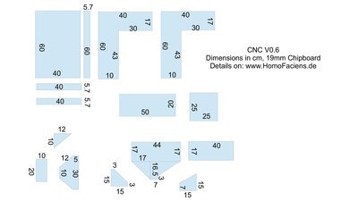
Chipboard parts. 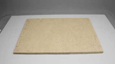
The construction is based on 19mm chipboard - relicts from an old chest I am sawing up for my machines. The dimensions of the base plate are 40x60cm. 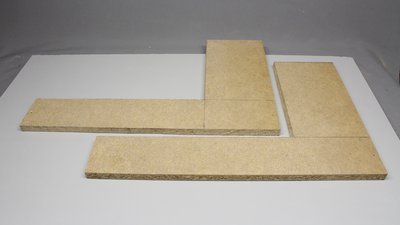
Side frame. 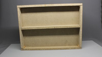
Bottom view. 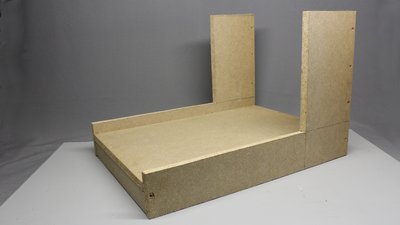
Base of the machine. 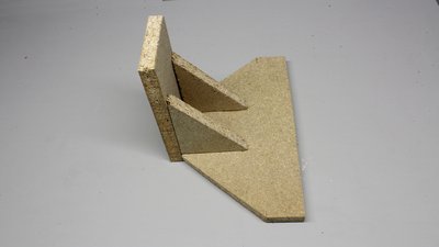
Moving part of the vertical axis. 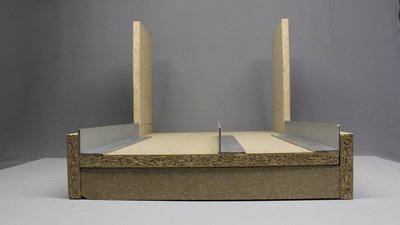
The linear guides are more solid than those of CNC v0.5 - the dimensions are 40x40x2mm. 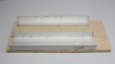
The plate of the X axis with the linear guides for the Y axis. 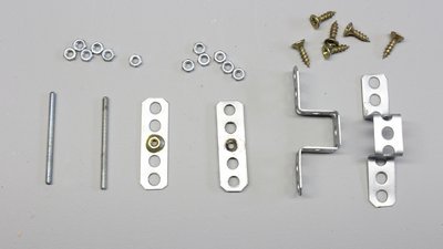
The movement is done through 3mm threaded bars. Two brass nuts have to be soldered on two pieces of perforated metal stripes. Using brass nuts in combination with iron bars reduces abrasion. The wear on the iron threads is lower than that on the brass nuts, thus the treaded bars won't get destroyed over time. On the other hand the cheap brass nuts might have to be replaced after several hours of operation. 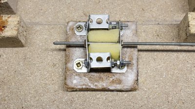
The second metal stripe is mounted in such a way that the clearance is as low as possible. The lower the clearance, the higher the friction. The right adjustment is a compromise between friction and clearance. The sponge is an oil reservoir. The threaded bar should always be covered with some lubricant to reduce friction. The tiny wooden plate is penetrated with wachs to prevent the oil from entering the wood. Better is the solution I am using at my CNC v3.2 (watch my YouTube Video). 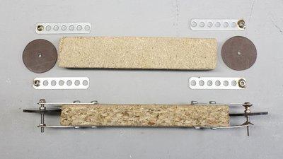
In principle, the axes can run on the aluminum bars. To reduce friction, I have cut 8 plastic discs with a diameter of 37mm. 3mm screws operate as pivot axes. The bearings are made of brass tubes with an inner diameter of 3mm soldered to a stripe of perforated metal (top left). You can also solder M3 nuts with the inner thread remuved by a 3mm drill (top right on the picture). 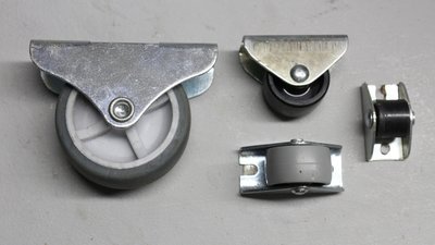
Instead of the self made plastic discs, you can use tiny wheels available in all hardware storesor ball bearings. Even the cheap wheels or ball bearings are usually from better quality than the discs I have cut, but I like the idea of using a CNC to improve it's own design - it's machine evolution... 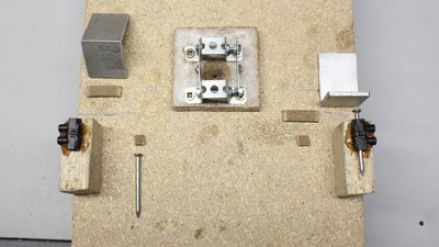
The guiding mechanism along the middle aluminum bar is different from that of v0.5. Small pieces of hardboard (maybe card board can be used, too) are glued on aluminum angles and nail heads. The aluminum linear guide slides between the pieces of hardboard. 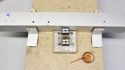
Adjust the aluminum angles straight with a bar when gluing them to the plates of the axes. 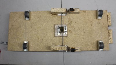
The bottom of the X axis. With the upgrade to version 0.6.1 I have replaced the self cut plastics discs by 30mm wheels from a hardware store. 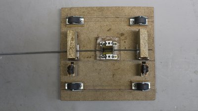
The bottom of the Y axis. 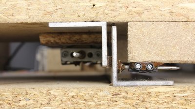
Linear guide of the X axis. With the screw terminal the nail can be adjusted to reduce clearance. Penetrate the hardboard with oil to reduce friction. 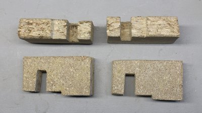
With upgrade to V0.6.1 I have enforced the aluminum angles of the linear guides with pieces of 19mm chipboard (see figures 15 + 16). 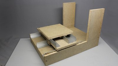
The plates for the X and Y axis with the linear guiding mechanism. 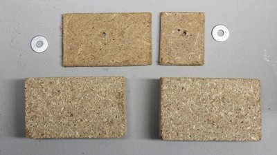
Attachment for the treaded rods. 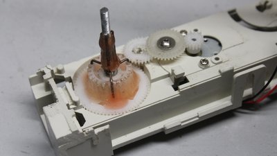
The linkage between the motor and the threaded rod is made of a paper clip and some epoxy. A short piece of a 3mm rod is glued on the gear wheel at the output shaft of the drive. 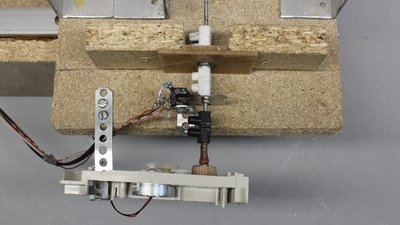
Adjust the screw terminals to minimal clearance and put some lubricant on the mechanism. 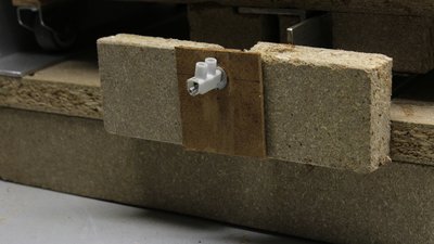
After upgrading to version 0.6.1 the threaded rods are guided at both ends. with the screw terminals the rods are prestressed. The more prestress, the less clearance, but the more friction. I am using the motors of an old printer to overcome the higher friction of the prestressed threaded rods. 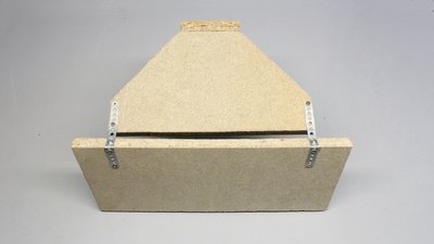
The hinges for the vertical axis consist of two stripes of perforated metal. 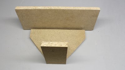
Mechanism of the vertical axis. 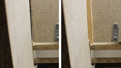
There are gifted woodworkers that can cut more precisely than I can do... I am bridging those gaps with 10x10mm stripes of wood. 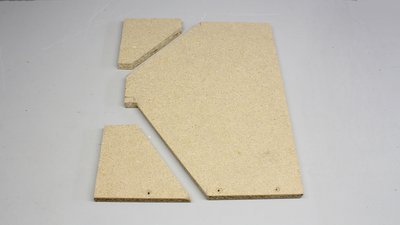
Parts for the mount of the servo for the vertical axis. The piece at the bottom left is an enforcement at the back of the machine frame (see figure 32). 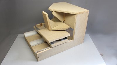
The completed mechanics. 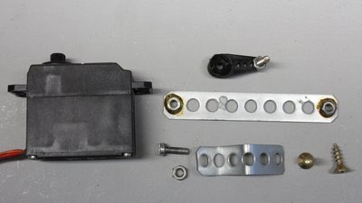
Parts for the linkage between servo and vertical axis. 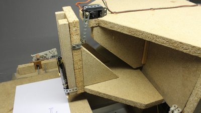
Servo mount. 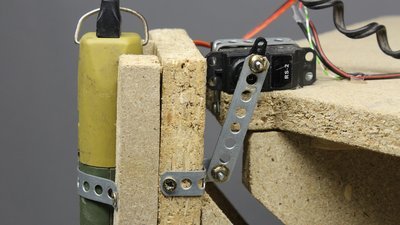
With upgrade to V0.6.1 I have attached the vertical axis as close as possible to the pivot point of servo lever. 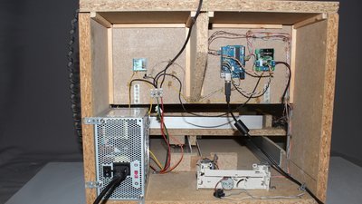
The electronics at the back of the machine. 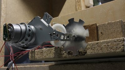
With V0.6.1 the sensor discs have 8 teeth. The plate of the upper table had to be cut, ... 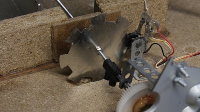
... while the base plate was milled out at the disc position. 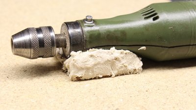
Some filler is used to mount the router with low clearance. Grease the router to be able to remove the hardened filler from the motor! 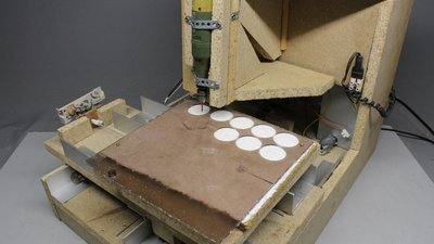
First test runs with 3mm plastics. 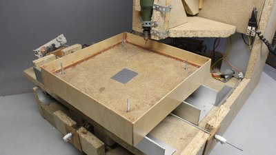
The chipboard bulges when sprinkled by too much splash water, which is defenitely not good for the precision of this machine. I have build a curb from plywood and sealed it all with varnish. 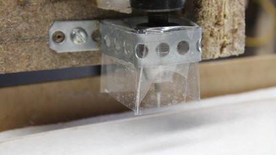
The splash guard is made of a perforated metal stripe and some plastics. Test pattern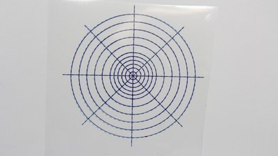
This test pattern was plotted using a pall pen. The plot is compared to the same pattern printed on a foil using an ink jet. 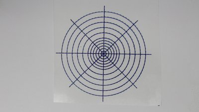
This is the test pattern plotted with V0.6.1. Examples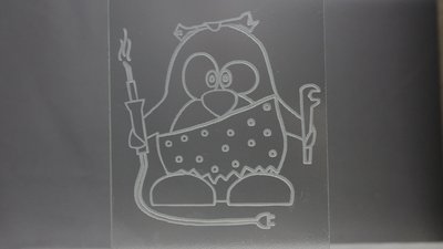
Engraving glas is very precise, because there is almost no side load on the diamond cutter. 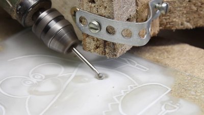
The router isn't mounted perpendicularly to the cutting plane, but with an inclination. The diamond milling cutter should always be cooled. I am using water with some drops of dish liquid. 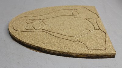
You can engrave and cut wood. Note that the router bit heats up strongly whenever it dives too deep into the chipboard, as can be seen on the smoked wood along the cutting line. This machine is not made for cutting wood with a thickness of more than 5mm. 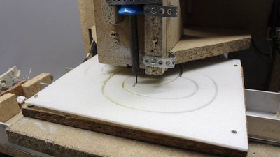
3mm Depron is easy to process. The machine can cut the material with maximum speed. Put a second layer of waste Depron underneath the material to be processed to avoid the router bit from diving into the wood. You can also melt Depron using a soldering iron with a 1mm copper wire at its tip. Thats much more quiet. The heat at the tip depends on the length of the copper wire and it must be enough to melt the Depron, but no more. Too much heat widens the cutting line and increases the bad smell of evaporating plastics. Depron is a propper material to demonstrate the working principles of a CNC. Besides the fact that it is easy to process it is very cheap. 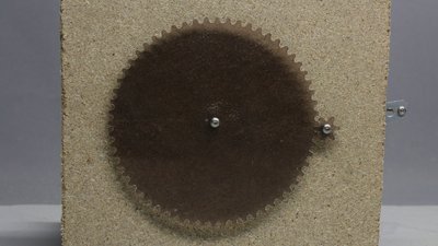
The gear wheels cut from 3mm plastics have round teeth that are calculated by the software using several parameters. Always cool the material with water to avoid the plastics from melting and cut the material in several steps. Parameters such as feed rate or cutting depth depend on the material to cut and are empirical values. My first attempts in cutting plastic were failures. You have to make your own hands-on experience with a CNC machine and in doing so, you will scrap more than just one part... The gearwheels are not perfectly shaped, but they are good enough to demonstrate the working principle of a transmission. This simple gearbox is not for high speeds or high torque. 
The 1mm aluminum brings the machine to it's limits. The result is eventually acceptable, but definitely not very good. I will try to improve the design to get better results - let's see what this cheap machine is good for in the future... 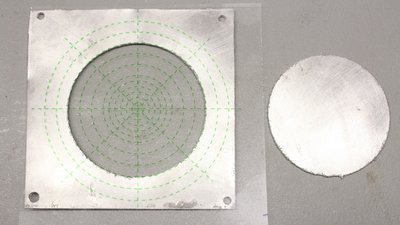
With V0.6.1 I have cut this 6cm disc with a very low feed rate (20 minutes cutting time). The result isn't too bad, considering the low quality bit and the low power machine. But just have a look at the rough cutting edge before you think you could process solid aluminum with this CNC! 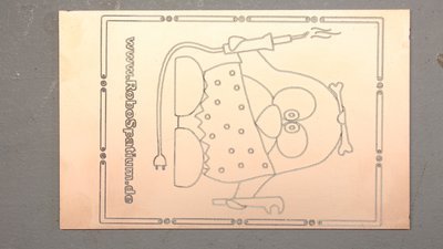
The overall precision of this CNC is not good enough to mill PCBs. Because of the fact that neither the board, nor the machine is dead flat, the width of the groove varries. The copper of some soldering points is teared, by what the result is useless. At least you can use this machine to decorate a copper plated board - nothing more, yet. Electronics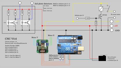
Schaltplan. 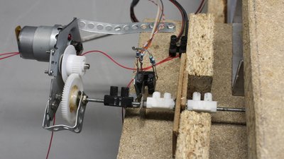
The H bridges typr L298N used for this machine are designed for a continuous current of up to 2A. This drive is from an old ink jet printer and it is more powerful than the geared motors from the optical drives. We get up to 4mm per second instead of 3mm per second with the weaker motors. Software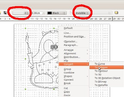
The software used to control the machine is written in C and it is running from the command line. With the menu you can choose the test pattern and set some variables. The supported vector format is "Scalable Vector Graphics (*.svg)" with some special things to note: No areas are drawn, only their outlines. All paths (also the outlines of an area) must be set to "Polygon". I have tested the functionality with graphics edited and exported as svg by Libre Office Draw. You can get the source code with some example vector files at the Download section. News The Project Technology RoboSpatium Contribute Subject index Archives Download Responses Games Links Gadgets Contact Imprint |
|||||||||||||||||||||||||||||||||||||||
|
|