|
|
|
|
News The Project Technology RoboSpatium Contribute Subject index Download Responses Games Gadgets Contact CNC v2.0The video about CNC v2.0Version 2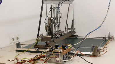
Time to overhaul my first CNC machine. Hardware revision number 2 should become more compact, because I never used more than a quarter of the 100cm x 200cm working area of the previous machine. A more simple construction and using simple DC motors instead of the stepper motors were also part of the new specification sheet. The result is a machine with a base plate of the dimensions 80x80cm with a working area of approximately 50x50cm, that is controlled through an USB interface. 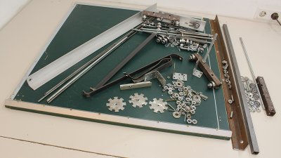
Besides other parts I used some ball bearings, threaded bars as well as aluminum and iron bars and tubes to built the machine. 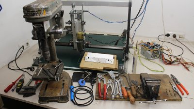
The main tools used are a drill press, a vice, a metal saw, some file tools, wrenches and a set of 6mm taps. Parts list
Tips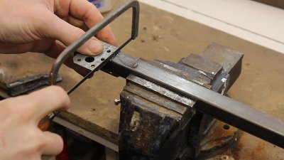
You can cut the iron bars by using an angle joint as guide for the saw. Cooling the sawing blade with some water extends the lifespan of that tool. 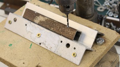
At the construction shown here, some drill holes are done on the edges of the square tubes. In order to make those holes I am using two aluminum angles on a wooden plate as guide for the iron tube. With a second wooden plate the construction is attached to the drill press. The edge of the iron square tube is filed and the place for the drill hole is marked with a center punch. The drilling is done in three steps, starting with a 3mm drill, than 6mm and finally 10mm. 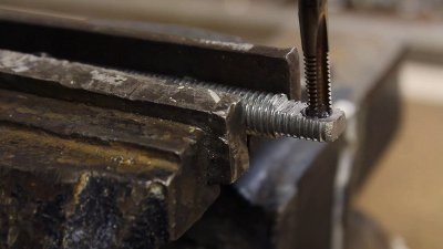
The axes are driven through 6mm threaded bars. We need some 10mm bolts with a 6mm thread at one end. To get that, the 10mm bolt has to be filed flat on two opposite sides. Now, a 5mm hole is drilled. Counterbore the hole with a 6mm drill. The threat is cut next. 3 taps are needed. The first cut is done with the tapper tap, usually marked with one ring at the shaft. Put some lubricant on the tool. Assure that the tap is aligned perpendicularly. After turning the tap clockwise for some degrees, turn it counterclockwise to break the chip formed through the cutting process, thus to prevent the tool from jamming. The second run is done with the intermediate tap, marked with two rings at the shaft and finally the third run is done with the bottoming tap, usually marked with no ring, sometimes with three rings at the shaft. Now, a 6mm bolt should easily fit into the hole. Tip from 'Schnipp': Take a M10 nut,and screw it on the Bolt where you want the hole. Put it in a vise,so that one of the nut's surface is in a 90°(shows up) position. Then you easyly mark it with a center punch right in the middle of nut's surface and bore right throu both together.You also have to cut the Tap in the same way. After loosen the nut,you have your die exactly in the center of the bolt and nothing to file. You also can after that bore the oil hole,just turn 90° 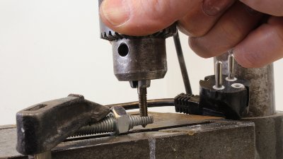
The alignment of the taps becomes simple when replacing the drill bit by the tap after drilling and counterboring the hole. Unplug the drill press and turn the chuck by hand (e.g. at the pulley) or else your tap will be destroyed in seconds! Don't forget to periodically turn the chuck clockwise and counterclockwise and to put some lubricant on the tool. This assures right angle threads without relying on my wobbly hands and bad eye for perpendicular work (that's what Fred wrote me - thanks for that tip!). Mechanics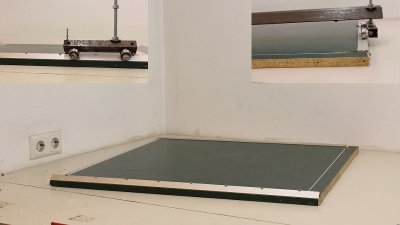
The base plate with the dimensions 80x80cm is cut from an old table tennis table with two aluminum bars at two edges. At one edge the aluminum angle profile is fastened with the tip pointing to the top while it is fastened with the flat side at the opposite edge of the base plate. 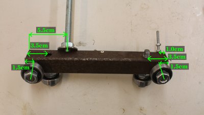
Four ball bearings are attached to a 20cm piece of a square tube. The 10mm holes are drilled with a distance of 1.5cm respectively 3.5cm from the ends. The drill hole at the edge of the square tube with the 50cm threaded bar is 5.5cm away from the left end. The 4mm drill hole used to fasten the cross bar is 1.0cm away from the right end. 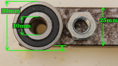
The inner diameter of the ball bearings is 10mm, the outer diameter should be clearly larger - I am using bearings with 30mm in total. The iron square tube has an edge length of 25mm - at least a 10mm nut must fit to the inside. The drill hole for the ball bearings should be close to the lower edge of the tube. Consider that the 10mm nut is used at the inside of the tube, thus the hole should not be too close to the lower edge. The outer diameter of the ball bearings must be clearly below the edge of the iron tube. 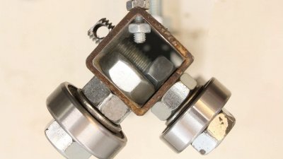
There must be an offset between the drill holes at two sides of the tube, because the bolts and nuts used to mount the ball bearings should not get in touch. 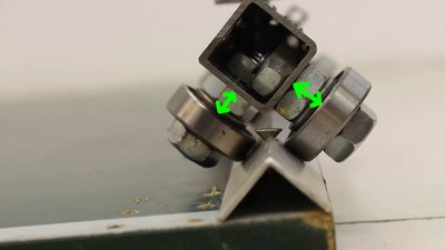
Note that the space between the square tube and the ball bearings must be large enough so that the bearings don't touch the screws used to mount the linear guide on the base plate. 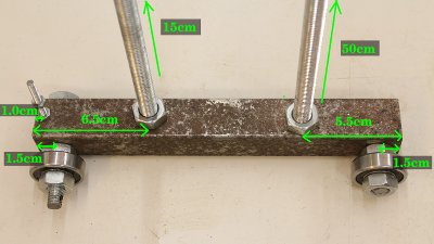
The second half of the X carriage. 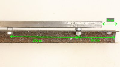
Both halves are connected through a compound made of a 85cm long angle profile with an edge length of 40mm and a thickness of 4mm and a square tube of the dimensions 20x20cm. 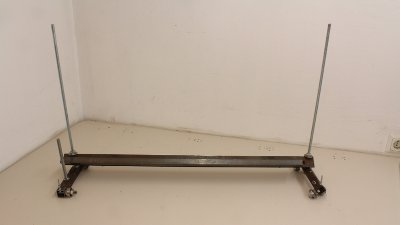
The corner steel bar is touching the first half of the carriage... 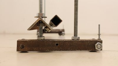
...while the height is adjustable at the second half. 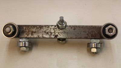
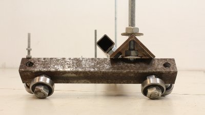
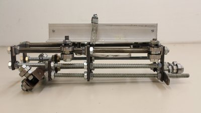
The Y carriage is also based on a 20cm long piece of a square tube with an edge length of 25mm: The drill holes for the ball bearings are 1.5cm respectively 3.5cm away from the ends. The drill hole for the 10mm bolt with the 6mm thread used for the drive is at the center of the square tube. 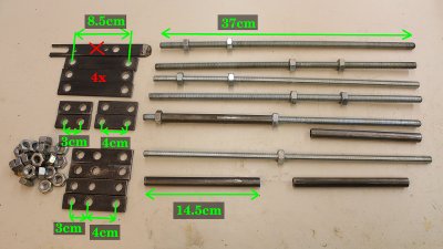
The main components of that carriage are some 37cm long threaded bars with a diameter of 10mm being connected through flat iron bars. 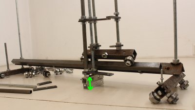
Assemble the structural component in such a way that there is a space of 4 to 5cm between the base plate and the lower edge of the Y carriage. 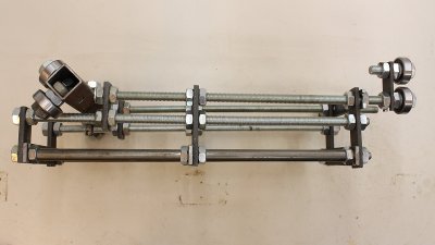
The iron tubes at the front of the Y carriage (bottom of the photo) must fall in line. 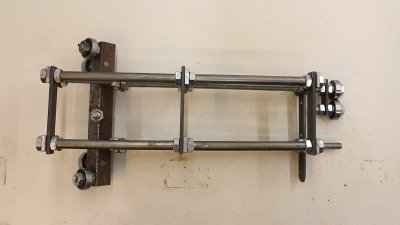
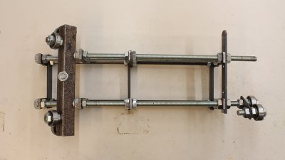
The carriage is guided by an aluminum angle profile with an edge length of 40mm and two more ball bearings at the top of the construction. The movement along the X and Y axis must be smoothly and free from clearance. 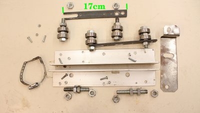
The Z axis is guided by ball bearings running on round tubes. That carriage is based on two pieces of 40x40x2mm aluminum angle profile with a length of 26cm. 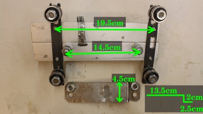
With the slot at one end of the flat iron bars (top of the photo) the width between the ball bearings can be adjusted to minimize the clearance. 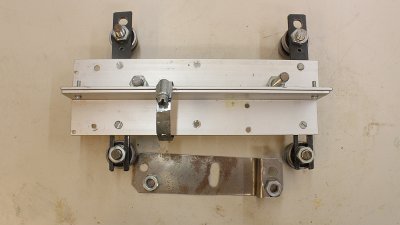
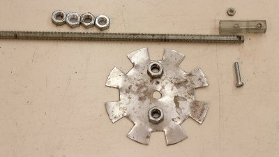
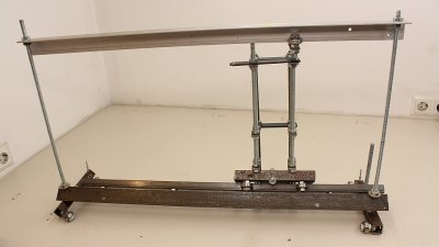
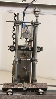
The 6mm threated bars with a length of 85cm are mounted next. The diameter of the sensor disc is 7cm. 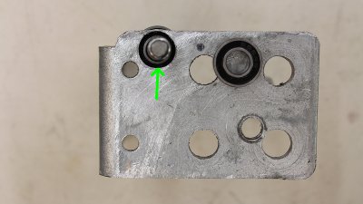
One fastening point consists of two iron angle joints. The treaded bar is mounted using four nuts and two ball bearings with an inner diameter of 6mm. 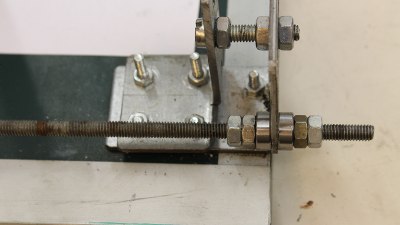
One ball bearing is to the left and one to the right of the joint. Tight the third nut so that both ball bearings are pressed against the angle joint. The higher the torque used to tighten the nut, the more friction, thus it becomes harder to turn the treaded bar. If you have found the right adjustment, lock that nut with nut number four. That end of the threaded bar should be free from clearance. 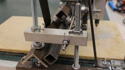
Those ball bearings are attached to an aluminum angle profile at the Y axis. 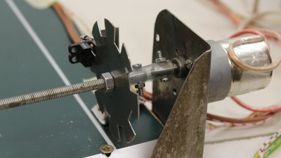
The sensor disk and the drive are at the opposite end of the treaded bar. The geared motor is connected to the threaded bar through a piece of rubber tube (fuel pipe with an inner diameter of 5mm). Thus, that connection is flexible. Threaded bars from the do-it-yourself store are usually not dead straight, thus with the flexible link the drive runs smoothly even with a buckled bar. 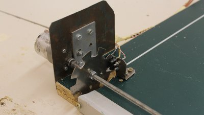
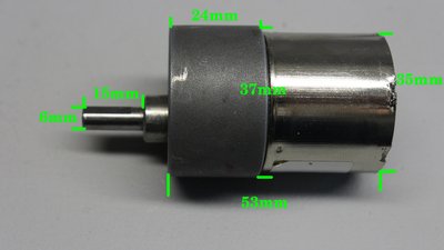
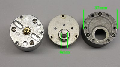
Technical data of the brushed DC motors: Diameter: 37mm Shaft diameter: 6mm Operating voltage: 12V Idle speed: 200U/min Torque: 60Ncm Gear ratio: 30:1 Maximum current 2A 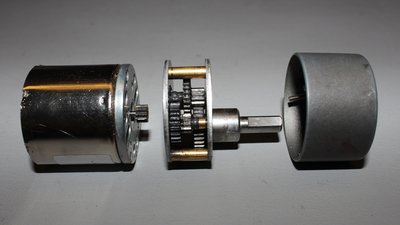
The threaded bar for the drive of the Z axis is only connected with the geared motor. It's gravity that pulls that carriage downwards by what the the clearance of that drive is negligible. 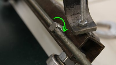
The carriages are connected to the drive through the 6mm threads in the 10mm bolts. If that thread is adjusted straightaway, the drive runs smoothly, but there is a noticeable clearance. By turning the 10mm bolt slightly, the friction is increasing, but the clearance is lowered. Adjusting the drive is always a compromise between friction and clearance. To reduce friction, put some lubricant on the threaded bar. 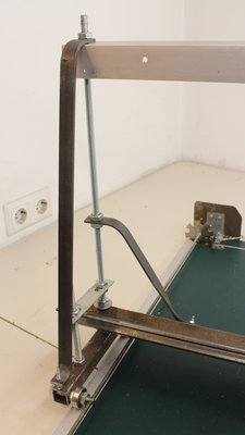
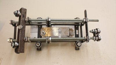
Two bars are used to stiffen the construction... 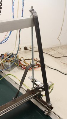
...at both ends of the X carriage. 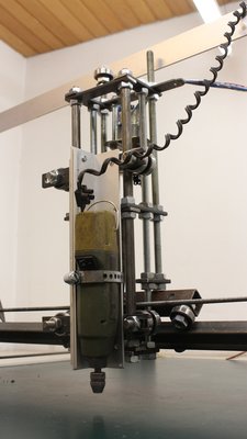
The machine was built to work as CNC router. 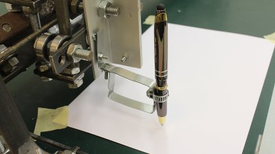
When attaching a ball pen or a marker at the Z carriage, the machine can also be used as plotter. Caused by the low speed (less than 3mm per second), that machine is not a fast printer... 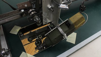
When adjusting the router in a tilted position with thin, flexible 3mm threaded bars, you can engrave patterns on a glass plate using a diamond milling cutter. 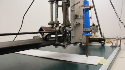
With a 1mm copper wire at the tip of a soldering iron you can cut Styrofoam. Srdjan gave me a tip: You can add a tiny fan near the tip of the cutting wire that blows away the hot air which makes the cut more consistent. Accuracy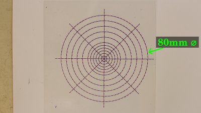
Test plot with a ball pen. Overlay with a foil printed by an inkjet (red dotted lines). 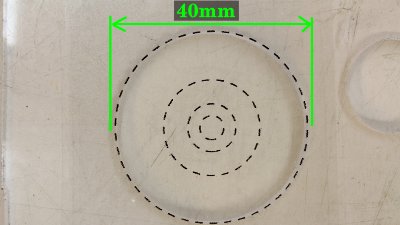
Cutting 4mm acrylic plastic in two steps. Pattern at the "hard" end of the X and Y axis... 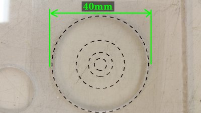
...pattern at the "felxible" end of the X and Y axis. 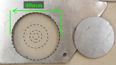
Cutting 0.8mm aluminum plate. Compressed air can be used to remove the chips and so to clean the CNC machine after usage. Tip from Matt: If you don't have a compressed air line, a dry (or paraffin wet) paintbrush works well for cleaning the crud out of threads. Electronics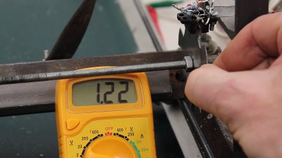
The gear ratio of the DC motors is 30:1 and the maximum current running through the windings is 1.2A at 12V operating voltage. 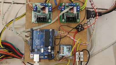
The motors are controlled through 4 H bridges - each of the two boards used here has two bridges using a L298N IC. The control pulses are generated by an Arduino Uno which computes the current position of the motors via the 8 photo sensors. I have demonstrated that principle in detail in the chapter about the Arduino Uno microcontroller. A relay, controlled though a small signal transistor by the Arduino is used to switch the router. 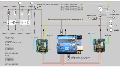
After connecting the electronics, you should start the motors by software for the first run carefully (one after the other). If one of the motors starts spinning continuously, you must swap the terminals at the accordant H bridge. Software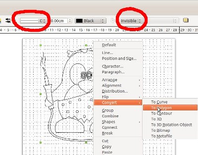
The software used to control the machine is written in C and it is running from the command line. With the menu you can choose the test pattern and set some variables. The supported vector format is "Scalable Vector Graphics (*.svg)" with some special things to note: No areas are drawn, only their outlines. All paths (also the outlines of an area) must be set to "Polygon". I have tested the functionality with graphics edited and exported as svg by Libre Office Draw: 1.) Draw graphics witth LibreOffice Draw. 2.) Press Strg + 'A' to mark all objects. 3.) Click on "Modify -> Convert -> To Polygon". 4.) Set line attributes to "Continuous" and to black color. 5.) Set Filling to "Invisible". 6.) Export as *.svg 7.) Copy the file to the subdirectory "pictures" in the installation folder of the CNC software. You can get the source code with some example vector files at the Download section. Frequently Asked Questions (FAQ)
News The Project Technology RoboSpatium Contribute Subject index Archives Download Responses Games Links Gadgets Contact Imprint |
|||||||||||||||||||||||||||||||||||||||||||||||||||||||||||||||||||||||||||||||||||||||||||
|
|