|
|
|
|
News The Project Technology RoboSpatium Contribute Subject index Download Responses Games Gadgets Contact <<< Demultiplexer Digital ruler >>> Read switching statesThere is no Video about reading switches available, yet.Leave a comment, if you have ideas of what to show in that video (besides the things already mentioned on this page).OverviewIn this chapter you can read about:
"0" or "1"?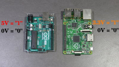
In this chapter I will show you how to read the status of switches. This is done by reading whether the respective logic voltage or 0V is present at a GPIO. This logic voltage is e.g. +3.3V with the Raspberry Pi and +5V with the Arduino UNO. The voltage is always measured between the relevant GPIO and the ground pin of the computer or microcontroller used. The maximum logic voltage on a GPIO must never be exceeded, as this will immediately destroy your computing device! If 0V is present, the software usually returns a logical "0"; that voltage level is also referred to as a LOW signal. If the logic voltage level is present, the return value is a logic "1", that voltage is referred to as a HIGH signal. Hysteresis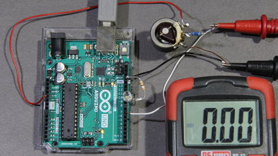
0V correspond to a logical "0", and 3.3V or 5V correspond to a logical "1". But what about voltage levels between these two extremes? This can be examined by using a potentiometer: The two outer terminals of the potentiometer are connected to ground and the relevant logic voltage, i.e. to +3.3V for the Raspberry Pi and to +5V for the Arduino. The middle pin of the potentiometer is connected to a GPIO via a 1kΩ protective resistor (why see below). To determine whether the software returns a logical "0" or a "1", an LED including a series resistor is connected to a second GPIO. What value the resistance must have and what else has to be considered when connecting an LED to a GPIO can be found in the chapter on switching LEDs. The two probes of the multimeter are connected to ground as well as the GPIO used as input. The potentiometer is now turned so that 0V can be measured on the GPIO. The LED is off. 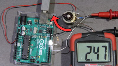
Now the potentiometer is turned so that the voltage at the GPIO rises slowly until the LED is switched on, inticating that the software returns a logical "1". This is the case at a voltage of 1.34V with the Raspberry Pi and at 2.47V with the Arduino UNO. 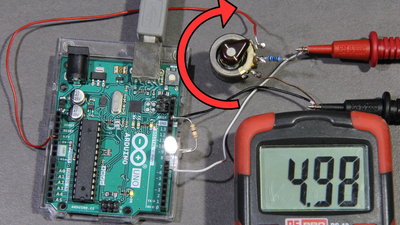
The potentiometer is next turned so that the maximum voltage is applied to the GPIO, i.e. 3.3V for the Raspberry Pi and 5V for the Arduino UNO. The LED remains on, the software returns a logical "1" above the previously determined threshold voltage. 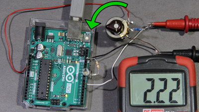
Now the potentiometer is turned in the opposite direction, with which the voltage at the GPIO slowly decreases until the LED is finally turned off again because the software returns a logical "0". This happens with the Raspberry Pi at a voltage of 1.17V, with the Arduino UNO at 2.22V. 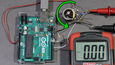
If the potentiometer is turned further down to 0V, the LED remains switched off. The software returns a logic "0" below the second determined threshold voltage. 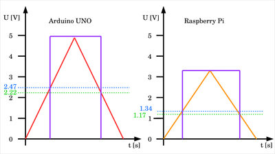
The difference between the upper threshold voltage and the lower threshold voltage is 0.17V for the Raspberry Pi and 0.25V for the Arduino UNO. The property that a GPIO switches from "0" to "1" at a higher level with rising input voltage than vice versa from "1" to "0" with falling input voltage is called hysteresis. 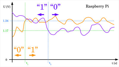
In real circuits there is always noise to be considered. The voltage is never constant, but instead superposed by small, random fluctuations. The hysteresis at the input of a GPIO prevents the return value of the software from jumping back and forth between "0" and "1" when the applied voltage is close to the threshold. However, this is only the case as long as the noise is less than the difference between upper and lower threshold. The voltage curve drawn in orange exceeds the upper threshold voltage for the first time at t1, as a result of which the return value of the GPIO jumps from "0" to "1". Due to the noise, the upper threshold is crossed several times, but never the lower threshold, which keeps the GPIO in the "1" state. The voltage curve drawn in purple drops below the lower threshold at t2 for the first time and crosses that line multiple times after that, but never again the upper threshold, so that the GPIO remains in the "0" state. Read switching states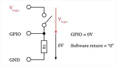
Probably the simplest case to read data via a GPIO is to evaluate the status of a switch. To do this, the two states OPEN and CLOSED must be converted to the states LOW (0V) and HIGH (5V for the Arduino UNO or 3.3V for the Raspberry Pi). In addition to a switch, an ohmic resistor is required. If the resistor is connected between ground and GPIO as shown here, the configuration is called a pull-down resistor. The switch is connected between the GPIO and the positive logic voltage. The GPIO is connected to the resistor and to the switch. If the switch is open, the GPIO is connected to ground via the resistor and a voltage of 0V is to be measured at the input. The resistor pulls the voltage at the GPIO down to 0V - hence the name pull-down resistor. With a pull-down resistor the return value of the software is "0" when the switch is open. 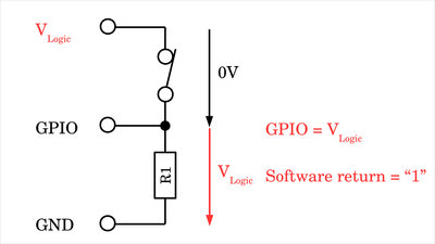
As soon as the switch is closed, there is a conductive path from the GPIO to the positive logic voltage. Switch and resistor form a voltage divider, whereby the ohmic resistance of the switch is close to 0Ω, but the value of the pull-down resistor is in the range of a few kiloohms. This means that almost the entire logic voltage drops across the pull-down resistor which equals the voltage level at the GPIO. As a result, the software returns a logic "1" when the switch is closed in a pull-down resistor configuration. 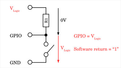
The second way to read the status of a switch is to connect the device between GPIO and ground and the resistor between GPIO and positive logic voltage. In this case one speaks of a pull-up resistor. With the switch open, the GPIO is connected to the positive supply voltage via the resistor, so that this is applied to the pin. The resistor pulls the voltage at the GPIO up to the value of the logic voltage - hence the name pull-up resistor. When the switch is open, the software returns a logic "1" using a pull-up resistor. 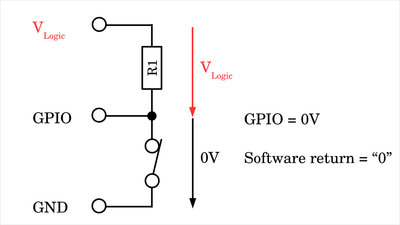
If the switch is closed, it also forms a voltage divider with the resistor. With the almost non-existent resistance of the switch more or less all the voltage drops accross the resistor so that in return the reading at the GPIO drops to (almost) zero volts. With a pull-up resistor the software returns a logic "0" when the switch is closed. The value of the pull-up or pull-down resistor used should be in the range of a few kiloohms in order to keep the current flow as low as possible when the switch is closed. Internal resistors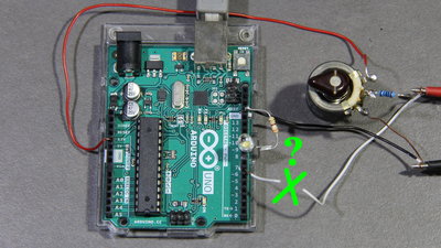
If a GPIO is switched to input mode without external components being connected, the return value of the software is not defined. The internal resistance of the GPIO in this state is very high and even the smallest variation causes the return value to tilt in one direction or the other. This state is therefore referred to as floating, Hi-Z or tri-stated. 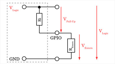
A precisely defined state, even of an open GPIO, is obtained, as already shown above, by a pull-up or pull-down resistor. Most GPIOs are equipped internally with such resistors, which can be enabled or disabled if needed. The value of these resistors is usually in the range of a few kiloohms and is listed in the data sheet. You can also determine the resistance value with a quick experiment: A resistor of about ten kiloohms is connected between ground and the relevant GPIO and the pull-up resistor is activated by software. This connects the GPIO to the positive logic voltage via the internal resistor. The GPIO is connected to ground via the external resistor, which gives us a voltage divider. The logic voltage and the value of the external resistance are known. If the voltage at the GPIO is now measured, the value of the internal pull-up resistor can be calculated using Ohm's law: RPull-Up / RExtern = VPull-Up / VExtern with VPull-Up = VLogic - VExtern you get: RPull-up = RExtern * (VLogic - VExtern) / VExtern 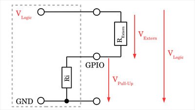
The experiment can be modified slightly to determine the value of the internal pull-down resistance. To do this, the external resistor is connected between GPIO and positive logic voltage with the internal pull-down resistor being activated by software. The voltage between GPIO and ground is measured again - which now corresponds to the voltage drop across the internal resistor - and the following applies: RPull-Down = RExtern * VGPIO / (VLogic - VGPIO) The Arduino UNO has no internal pull-down resistors. With the Raspberry Pi, either an internal pull-up or a pull-down resistor can be activated by software. Voltage readings Raspberry Pi and Arduino UNO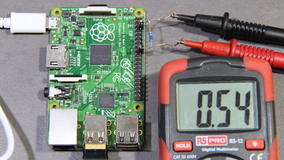
I did the experiment with a Raspberry Pi and an Arduino UNO and got the following readings with an external 10kΩ resistor:
Protective resistor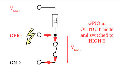
Software is never free from errors! Therefore, you should always design your circuits so that there is no damage even if a GPIO is accidentally activated in output mode, even though it is connected to a circuit designed as an input. The switch with an external pull-up resistor serves as an example: If the GPIO is mistakenly switched as an output and a HIGH signal is applied, there is a very good conductive path to ground when the switch is closed. A too high a current flows out of the GPIO (source current), which immediately destroys your computing device! 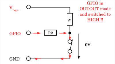
Another resistor that is connected between GPIO and the switch can help. If the GPIO is now defined as an output and on HIGH signal with the switch closed, the additional resistor limits the current flowing out of the GPIO. The resistance must be selected so that the maximum current of the GPIO is not exceeded. A good value is 1kΩ. 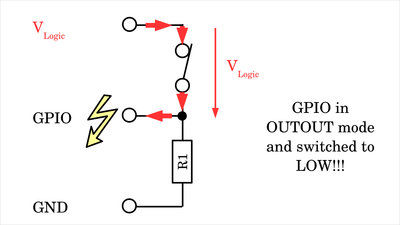
The situation is similar when using a pull-down resistor: Now there is a danger when the switch is closed, the GPIO erroneously in output mode and LOW signal is applied to the pin. Here, a too high a current flows into the GPIO (sink current). 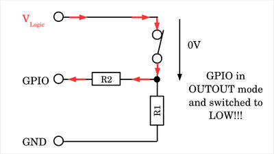
Again, the additional series resistor protects the GPIO and it should also be noted that it must be large enough to reduce the current to a safe level. 1kΩ is a usually good value for a protective resistor. 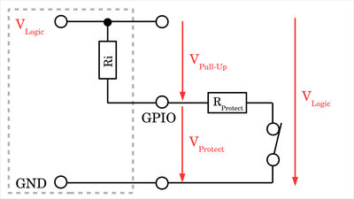
If you are working with the internal pull-up or pull-down resistors, a series connection is created when the switch is closed! For the voltage at the GPIO there is: VGPIO = VLogic * RProtect / (RProtect + RPull-Up) Since the internal resistor cannot be changed, the protective resistor must be chosen to be significantly smaller. At 20mA maximum current per GPIO for the Arduino UNO, the resistance value should be at least 5V / 0.02A = 250Ω. As shown above, the Arduino reliably returns a logic "0" at voltages below 2.22V. Furthermore, the internal pull-up resistor at the GPIO was determined to be 38kΩ. This results in a maximum value for the protective resistor of: RProtect = RPull-Up * VLogic / (VLogic - VGPIO = 38kΩ * 5V / (5V - 2.22V) ≈ 30kΩ Even with a protective resistor of 10kΩ, the lower threshold voltage is reliably undercut. 1kΩ are also a good choice when using the internal pull-up resistor. For the Rasberry Pi, 3.3V / 0.016A = 220Ω result as the minimum value. With internal pull-up / down resistors of around 50kΩ, the voltage thresholds are reliably exceeded or undercut at a maximum value of up to 20kΩ. 1kΩ is also a good choice for the Raspberry Pi as a protective resistor. Internal and external Pull-Up/Down resistors simultaneously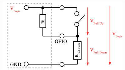
Another problem with faulty software occurs when using internal and external pull-up / down resistors at the same time. Here you can see the configuration using an external pull-down resistor with an erroneously activated pull-up resistor: When the switch is open, the two resistors form a voltage divider, which means that the voltage at the GPIO is by no means pulled to ground as expected. Depending on the resistance values, the threshold voltage is not undercut and the software returns a logical "1" even when the switch being open! The problem is basically the same with an external pull-up resistor and an erroneously activated internal pull-down resistor. With this combination, the threshold voltage is not exceeded, which means that a logical "0" is returned even when the switch is open. 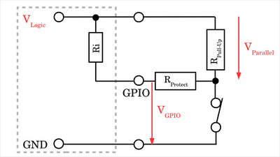
If an external pull-up resistor with series resistor for current limitation is installed and the internal pull-up resistor is also activated by mistake, the problem already described in Figure 21 arises with the resulting series connection of protective resistor and internal pull-up resistor when the switch is closed. If the protective resistor is too high in relation to the internal pull-up resistor, the lower threshold voltage is not undercut even when the switch is closed. If your program does not work as intended, it is always advisable to check the voltage level at the GPIO while the program is running with the switch open and closed! Contact bounce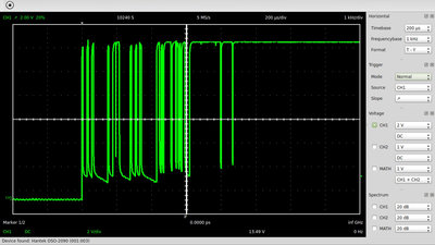
I already explained the effect of contact bounce in the chapter about switches and relays: The switch contacts are usually made of springy metals. Caused by the elasticity of the material, the contacts bounce apart several times before making steady contact whenever they strike together. As a result of the contact bounce, a rapidly pulsed current is running through the switch instead of a clean transition from zero to full current. When the switch is opened, the contacts rub against each other and an arc is formed (albeit with very small dimensions). These two effects also cause the voltage on the GPIO to jump up and down. When using mechanical switches in digital circuits, the contact bounce can be misinterpret as multiple switch action! 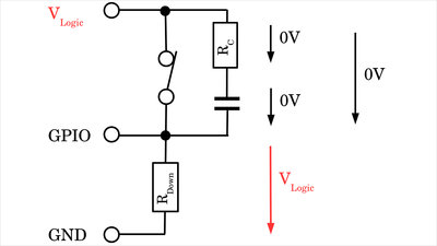
The jumping up and down of the voltage level at the GPIO can be suppressed by a capacitor-resistor combination connected between the two terminals of the switch. If the switch is closed in a configuration with pull-down resistor, the entire logic voltage drops between GPIO and ground. 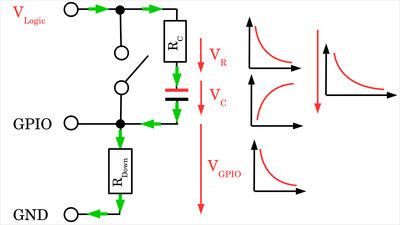
If the switch is opened, the pull-down resistor, the capacitor and RC form a series connection, as a result of which the voltage across the capacitor increases relatively slowly (depending on the resistance values of RPull-Down and RC). In return, the voltage across the pull-down resistor and thus also at the GPIO drops slowly. The voltage peaks caused by the contact bounce are smoothed and, due to the slowly rising voltage at the capacitor, the GPIO only crosses the lower voltage threshold once during the switching process. Accordingly, the software only recognizes a single transition from "1" to "0". 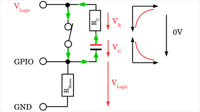
When the switch is closed, the capacitor is discharged via the additional resistor. At the GPIO, the voltage jumps to the level of the logic voltage. If the switch opens again briefly due to the bouncing, the voltage at the GPIO drops again to the value of the logic voltage minus (more or less) the current capacitor voltage. The resistance at the capacitor should therefore be chosen to be as small as possible. 1kΩ is a good value Without the additional resistance at the capacitor, a very high discharge current would flow out of the capacitor when the switch is closed resulting in unwanted voltage peaks! 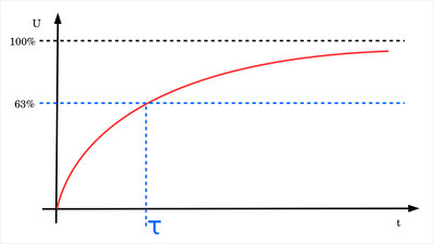
The larger the capacitance, the more reliably the peaks caused by bouncing are suppressed, but the slower the response of the system. If the capacitance is choosen too high, fast switching sequences are no longer recognized. Details about the voltage curve of charging capacitors can be found in the chapter about switching operations. The time constant is usually used as significant parameter: τ = R * C This refers to the period of time that elapses before a capacitor is charged or discharged to 63%. If the circuit is designated for a switching state changing up to 10x per second (more is hardly possible in practice with a mechanical switch), the product of resistance and capacitance must be less than 0.05s. With a pull-down resistor of 10kΩ we get as maximum value for the capacitance: C < τ / R = 0.05s / 10kΩ ≈ 5μF Since the bouncing usually only occurs in a time span of significantly less than 10 ms, the resulting lower limit is: C > 0.01s / 10kΩ = 1μF 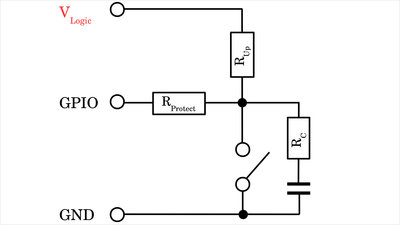
With a configuration using an external pull-up resistor and with a protective resistor in the event of unintentional activation of the GPIO as an output, we get the circuit shown here. Instead of using a capacitor-resistor combination, the problems caused by contact bounce can also be tackled purely by software. A HIGH signal at the GPIO is only interpreted as a logical "1" when it is present for a specified period of time (e.g. 5ms). The same applies to a LOW signal, which is also only returned as logic "0" if it lasts longer than 5ms. Sounds simple, but it also has its own pitfalls. Example circuits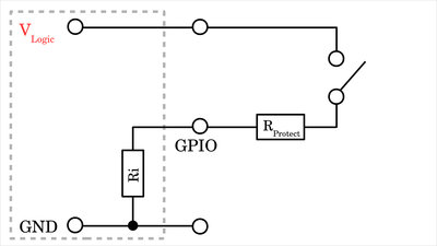
In the simplest configuration, only one resistor and one switch are required. The internal pull-up or pull-down resistor must be activated by software! Here you can see the version with internal pull-down resistor. Figure 21 shows the version with internal pull-up resistor. A resistance of 1kΩ is a good value for the protective resistor with both Arduino UNO and Raspberry Pi. 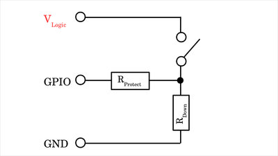
This is what the circuit looks like with an external pull-down resistor. With values of 1kΩ for the protective resistor and 10kΩ for the pull-down resistor, there are no problems even with inadvertently activated internal resistors with Arduino UNO and Raspberry Pi. Figure 18 shows the circuit with pull-up resistor, for which the same values can be used. 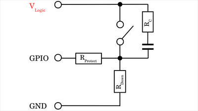
If contact bounce of the switch is also to be suppressed, 3 resistors and a capacitor are used in addition to the switch. With 1kΩ for both the protective resistor and the resistor at the capacitor and 10kΩ as a pull-down resistor with a capacitance of 1μF, reading even with not so good switches should work fine for Raspberry Pi or Arduino UNO. The circuit with pull-up resistor is shown in Figure 29. Sourcing partsWhen buying components via the affiliate partner links I have listed in the table (or through the banners on my pages) you help to keep my my projects going - many thanks!Clicking on the links does not mean you have to buy - you can simply browse through the pages ;-) Of course, supporting my freely accessible educational platform without shopping but by making a donation or becoming a Patreon also works. Many thanks to everyone who already sent me an obol! If you know more commonly available switches useful for the applications in this chapter, please leave a comment on this page.
<<< Demultiplexer Digital ruler >>> News The Project Technology RoboSpatium Contribute Subject index Archives Download Responses Games Links Gadgets Contact Imprint |
|
|