|
|
|
|
News The Project Technology RoboSpatium Contribute Subject index Download Responses Games Gadgets Contact <<< Read switches PICO Servo >>> Digital rulerVideo about the digital rulerMechanics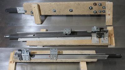
Most of the mechanics is build from pieces of a 40 times 40 mm aluminium bar, mounted on a 19mm particle board. 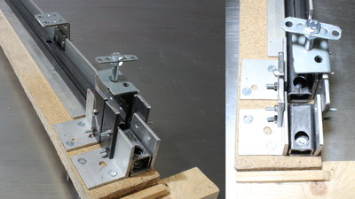
You can fix the square tubes on that guide with a screw. There are pieces of flat iron at the edges of the aluminum angles that guide the sawing blade while cutting. 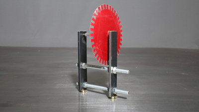
The sensor wheel is cut from paper and sealed with paint afterwards. The teeth are protected by adhesive tape from both sides. The axis is made of a 2.5mm nail. I pointed both ends with my drill press and a file. A piece of a rubber tube - usually used as fuel pipe for model engines - gives the axis a higher friction when rolling on a metal surface. Epoxi keeps the sensor wheel on the axis. The bearing of the axis is composed of two pieces of flat iron. Adjust the pressure on the ends of the axis with the 6mm threaded rods to reduce backlash but keep in mind that the sensor wheel must still spin with ease. With the rubber tube, the diameter of the axis is 6mm. The resulting circumference is approximately 19mm. To get a resolution of less than 0.2mm, we need more than 100 pulses per revolution. The sensor wheel I made has 36 teeth, resulting in 144 pules per revolution on the output pins of the two light sensors. With that we get an academical resolution of 130 micrometers per step - considering the backlash of the mechanics, an accuracy of approximately 0.5mm can be achieved. 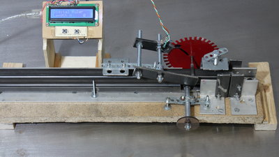
An Arduino Uno is used to count the pulses, displaying the result on an LCD. Keep in mind that the number of pulses per second, the Arduino can read, is limited. You can check if pulses are skipped with a simple experiment: Set a mark at one of the teeth. Now, move the square tube to the right quickly and slowly back to the left. If the counter reached zero, the marked tooth must be on the initial position. Move the square tube for a known distance to calibrate the unit - in the video I was using a distance of 40cm. With the number of pulses, you get the conversion factor. 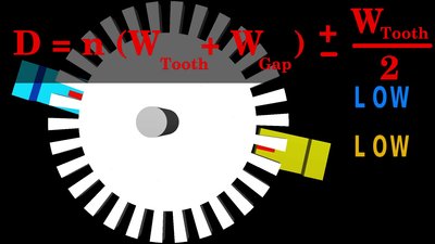
The second sensor must be an integer of the tooth and gap width plus or minus half a tooth width apart from the first one. Details are available inn the chapter about rotary encoders. If the distance between the sensors is given, we can in turn calculate the tooth width - the resulting minimal width is 2.4mm. To get a higher tolerance for the hand made sensor wheel, I am using a tooth width of 4mm, which also meets the requirement. Electronics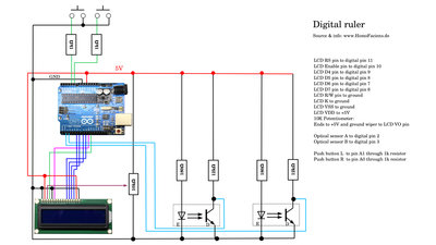
Schematics. One Arduino Uno, two push buttons, a 2x16 character LCD and a couple of resistors is needed to built the little helper. SoftwareYou can get the Arduino sketch at the column Download. Detailed explanations are in the source code.The optical sensors are connected to pin 2 and 3 of the Arduino, that operate as hardware interrupts. Whenever the signal at one of the pins changes from LOW to HIGH or from HIGH to LOW, a sub routine is executed, adding or subtracting 1 from the pulse counter depending on the direction of rotation. <<< Read switches PICO Servo >>> News The Project Technology RoboSpatium Contribute Subject index Archives Download Responses Games Links Gadgets Contact Imprint |
|
|