|
|
|
|
News The Project Technology RoboSpatium Contribute Subject index Download Responses Games Gadgets Contact <<< Digital ruler Xylophone >>> Raspberry PICO servoVideo about the PICO servoAbout the Pico Servo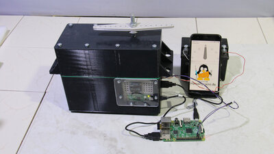
Servos are very useful components in many electromechanical projects which is why there are already some chapters on that on my website: With the servo based on the Raspberry Pico discussed in this chapter, I would like to deal with the electronics and software for controlling homemade servos in a little more detail. The mechanical design of the PICO servo is not perfect, instead the construction is based on an enlarged version of conventional RC servos. Nevertheless, a quite strong and really usable servo has been created, which can be controlled with the pulse width signal known from RC servos. Of course, the USB interface built into the Raspberry Pico can also be used for data transfer. Also thinkable are I2C or SPI or whatever you need and the Raspberry Pico can deliver. Parts listWhen buying components via the affiliate partner links I have listed in the table (or through the banners on my pages) you help to keep my my projects going without extra costs for you - many thanks!Clicking on the links does not mean you have to buy - you can simply browse through the pages ;-) Of course, supporting my freely accessible educational platform without shopping but by making a donation or becoming a Patreon also works. Many thanks to everyone who already sent me an obol!
Mechanics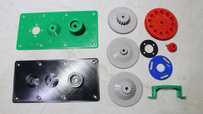
Almost all mechanical components are made of PLA with a 3D printer. 
Screws, washers, threaded rods, two ball bearings and other small parts are also needed. The axes for the gearbox have a diameter of 6mm. I used aluminum tubes because I had them in my stock. 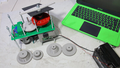
From the gears of the gearbox I created two variants: The first version had a 355:1 reduction with very high torque, but was clearly too slow, so I changed two of the gears, giving a total reduction of 177:1. With that, the lever rotates about three times the speed of the high reduction variant. 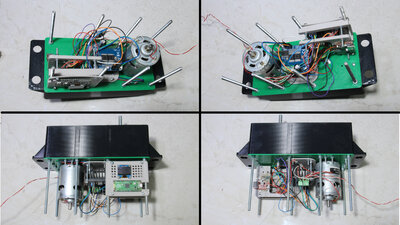
The electronic components are located in the lower area. Electronics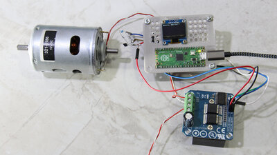
I got the motor as a gift from RS-Components years ago, but haven't used it yet - sometimes a project just needs a little longer to form. The electrical input power is supplied via an H-bridge type BTS7960. The already mentioned Raspberry Pico runs the control software. The 12V motor delivers up to 36W. For a little more comfort, I connected a 0.96 inch OLED display. 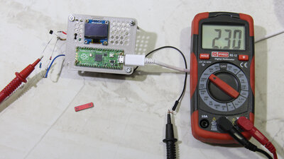
To give the Pico an idea of what is going on in its environment, three Hall sensors type AH3503 are used. These sensors provide an output signal that is equivalent to the strength and direction of the magnetic flux density passing through them. 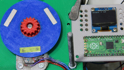
A sensor disc with 3 magnets is attached directly to the motor shaft. This disc is scanned by 2 Hall sensors - why 2 sensors are needed to detect the rotation, is described in detail in a previous chapter. 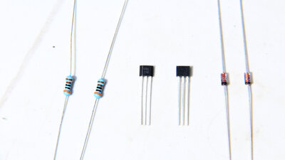
The Raspberry Pico works with logic levels of no more than 3.3V. A voltage divider composed of a 3 kilohm resistor and a 3V Zener diode prevents the logic voltage at the pin of the pico from being exceeded. Without a magnet, the corresponding pin returns a logical "1", while in the presence of a magnet with the south pole towards the Hall sensor, a logical "0" is returned. 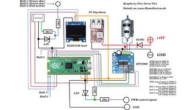
Circuit layout Wiper motor as servo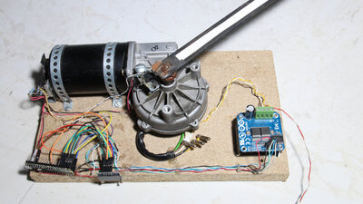
And if you don't own a 3D printer, you can also modify a wiper motor to turn it into a servo. Together with the OLED screen, the same pins are used on the Pico, only a few parameters in the software have to be adjusted. 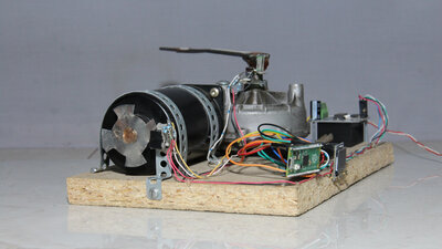
On the Mercedes motor (type SWF 4195B) I am using, the motor shaft sticks out at the rear end so that I could cut off the cap on the housing and glue a sheet metal sensor disk to it. This wheel is scanned by two infrared light sensors. 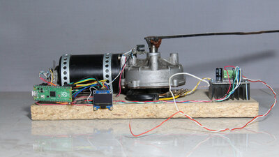
The reduction of the worm gear is 72:1. The limit switch for the servo lever is another photo sensor. SoftwareA special feature of the Raspberry Pico is the possibility of running small programs in an extra part of the chip, completely independently of the main program. This means that there are no interruptions from the main routine and the processing of the signals at the pins is extremely fast. I use this property to quickly process the input signals, both on the sensor disk and to read the servo control PWM signal at another pin. However, the command set of these mini-programs is very limited and the number of commands per program may not exceed 32 (jump labels do not count as command lines).The sensor disc on the engine is read out with the help of the first, so-called state machine:
With this program, only 2 of the 4 possible states are registered per tooth (magnet) on the sensor disc, which is due to the limited possibilities of the state machines - I did not manage to accommodate all 4 states in 32 command lines. The number of pulses determined here is multiplied by 2 in the main program. Furthermore, the current state of the two sensors is read in so that the intermediate states can also be calculated (through micropython code, not with the high speed of a state machine). The pulse width signal for controlling the servo is read in with the second state machine:
The complete source code in Micropython is available in the download package (see below). DownloadThe Download package (7.2MB) includes the software, the circuit diagram, as well as the 3D files of the mechanics.<<< Digital ruler Xylophone >>> News The Project Technology RoboSpatium Contribute Subject index Archives Download Responses Games Links Gadgets Contact Imprint |
|
|