|
|
|
|
News The Project Technology RoboSpatium Contribute Subject index Download Responses Games Gadgets Contact <<< CNC maschines Adjustable joints >>> Demonstration console industrial servo motorVideo about the Siemens driveSetup of my demo console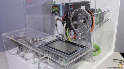
From Siemens I got an industrial grade servo drive. I am using this package to demonstrate the main difference between open and closed loop drives. The motor is a SIMOTICS S-1FL6, a brushless type powered by 230V, 3 phase alternating current. The electric input power is 0.75kW, which is around one horse power according to James Watt. The built in rotary encoder is clearly more sensitive than my DIY types: The two output lines deliver 10,000 pulses per full turn. The control unit is a SINAMICS V90PTI (B10-8UA0) with Pulse-Train-Interface from Siemens. Same as with my homebuilt drives, the position of this industrial servo motor is controlled through two input pins - one for the direction and one for the number of steps. Additional input pins on the interface allow for example to turn the drive ON and OFF or you can implement end switches. With the IOT2020 you can position the motor shaft exactly in the same way as I did with my selfmade drives - you only have to step up the 5V of the GPIOs through transistors to 24V, a common logic level in industrial applications. With the 24V input pins I am using in this demo console, the SINAMICS control unit can handle step pulses with a frequency of up to 200kHz. Through a second high speed input using 5V differential signals, up to 1MHz is possible. 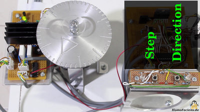
The driver board of the bipolar stepper motor is based on a LV8772 chip, capable of delivering a phase current of up to 2.5A - with the potentiometer on the board I have adjusted 420mA which is sufficient for this demonstration. The movement of the motor is controlled through two input pins. With two push buttons you can apply voltages to those inputs manually. 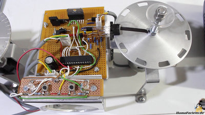
A sensor disc is attached to the shaft of the brushed DC motor. There are 10 holes at the edge so that the rotation of the disc can be scanned by two light sensors. If the light sensors are blocked by the disc, the output of the sensors is 0V - both LEDs are turned off. As soon as light hits the photo detectors through a gap in the disc, the output jumps to 5V - both LEDs are turned on. Depending on the position of the disc, the two outputs of the photo sensors change between four different states. Whenever the disc rotates until one of the outputs of the photo sensors changes, you can calculate the direction of movement. The angle of rotation is ruled by the number of teeth and gaps in the sensor disc. Whenever the disc rotates from one gap to the next, the state of the outputs changes four times. With a disc having 10 gaps, a full turn triggers 40 changes in output signals. One step equals a rotation of 9 degrees. The signals coming from the photo sensors and the external position command pins are read by a microcontroller type ATmega328P and so used to compute the control signals needed to switch the H bridge. More background infos on my pagesHow bipolar stepper motors work:Stepper motors How mechanical commutated DC motors work: DC permanent magnet motor More about rotary encoders: Encoder disc Transmissive optical sensors <<< CNC maschines Adjustable joints >>> News The Project Technology RoboSpatium Contribute Subject index Archives Download Responses Games Links Gadgets Contact Imprint |
|
|