|
|
|
|
News The Project Technology RoboSpatium Contribute Subject index Download Responses Games Gadgets Contact <<< DC motor (wound stator) AC motor >>> Stepper motorThe video about stepper motorsSpecial thanks to d85iDE for proofreading the video script! GeneralA stepper motor is an electric motor that divides its movement into a number of equal steps. The position of the motor shaft can be commanded to move and hold at any step without a feedback sensor.Bipolar stepper motorA bipolar stepper motor has usually two pairs, thus 4 terminals. Each pair of terminals is internally connected to a single coil or a group of coils that is connected in series or in parallel. Such a pair of motor terminals is called Phase. A bipolar stepper motor can be commanded using the polarity listed in the table:
The motor shaft moves in half stepping if the voltages at the motor terminals are changed to a nearby column of the table. The direction of rotor movement depends on whether you go from left to right or from right to left through the columns of the table. If the green marked columns are skipped, the motor moves a full step. If the red marked columns are skipped, the motor moves in full step mode, too, but during movement both phases are always "on". That mode is called two-phase on, full step excitation. The advantage of keeping both phases enabled is the higher torque produced by all four electromagnets during motor operation. The disadvantage is the doubled current flowing through the motor compared to the single-phase full step mode. 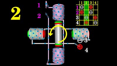
Stepper motor with 2 poles on the rotor. Terminal number 3 of the motor is connected to the cathode of the voltage source, terminal 4 to the anode. The upper end of the rotor is pulled to the bottom left, the lower end to the top right. The motor shaft moves counterclockwise by 90 degrees to align with the magnetic poles of the horizontal coils at the stator. 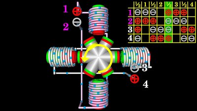
Stepper motor with 6 poles on the rotor. The step angle represents the rotation of the output shaft caused by each step, measured in degrees. The more permanent magnets on the rotor, the lower the step angle. With the motor of the drawing we get 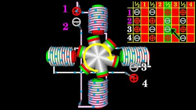
Stepper motor with 6 poles on the rotor in two-phase on, full step excitation mode. In that mode, both phases are always "on" and from one step to another, the polarity of one of the phases is changed. The rotational movement is 30 degrees per step which is equal to the normal full step mode. 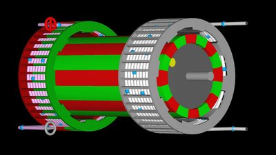
A bipolar stepper motor with a special design is the can-stack stepper motor. A phase of that motor is based on a bobbin wound coil design. The bobbin has claw teeth brought to the center that form the poles of the stator. If a current flows through the windings of the stator coil, magnetic poles are formed at the claws of the bobbin. Both stator cans have the same number of poles and the claws are arranged to be half a pole pitch apart. The motor shown here has 16 poles per stator can, thus the second bobbin is twisted by 11.25 degrees. The rotor is made of a permanent magnet with the same number of poles as one of the stator cans, thus we get 16 poles in this drawing. The rotor moves with each step to get in line with the poles of the enabled stator can. The north poles of the rotor are aligned with the south poles of the stator. Whenever phase 1 is enabled, phase 2 is disabled in full step mode. Because there is an offset of 11.25 degrees between both cans, which is half a pole pitch, the shaft moves the same number of degrees with each full step. The command sequence needed to operate the can-stack motor in full step, half step or 2-phase on mode is identical to that of the table above. Unipolar stepper motor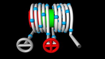
The coil shown here, has one winding with a center tap that is connected to the positive terminal of the supply voltage. If the left end of the wire is connected to the negative terminal, the current only flows through the left half of the coil. The magnetic north pole is created at the left side of the electromagnet. 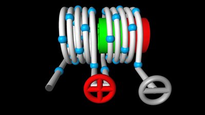
Whenever the right end of the coil is connected to the negative terminal, a current flows through the right half of the electromagnet forming the magnetic north pole at the right end of the solenoid. With the center tap, the magnetic pole of the electromagnet can be reversed without swapping the polarity at a pair of terminals. 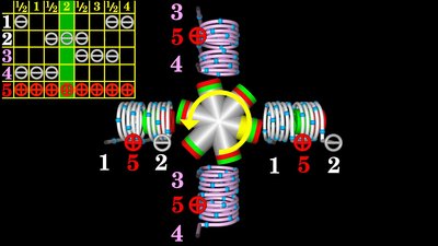
A unipolar stepper motor has usually 5 terminals. The center taps are connected to the positive terminal of the supply voltage. The coils on the horizontal axis at the drawing are switched in parallel. The left wire ends (1) are joined, which is also true for the right wire ends (2). Same is for the terminals (3) and (4) of the magenta colored electromagnet. The command sequence for a unipolar stepper motor with 5 terminals is as follows:
4 out of 8 halves of the electromagnets are enabled in a half step (50%). Unipolar stepper motors only utilize half of the coil length, so less torque is available to magnetically move or hold the rotor in place. To get (nearly) the same torque as with the bipolar type, twice the number of windings is needed which is why unipolar stepper motors are usually larger. Variable reluctance stepper motorMagnetic reluctance, or magnetic resistance is analogous to ohmic resistance in an electrical circuit. The rotor of a variable reluctance motor is made of ferromagnetic material with low hysteresis (e.g. soft iron). The magnetic resistance of soft iron is clearly lower than that of air. When a stator pole is energized, the rotor torque is in the direction that will reduce the size of the air gap in order to reduce the reluctance of the total magnetic circuit.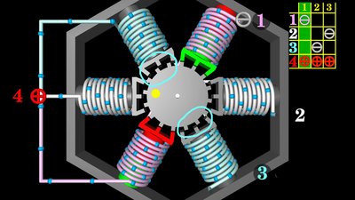
At the drawing, phase 1 of the motor is energized. In oder to make the rotor spin clockwise, phase 3 has to be enabled. A variable reluctance motor has usually 3 phases, thus 4 terminals. One of the terminals (4) is connected to one end of all coils in the motor. That terminal is permanently connected to the anode of the supply voltage during operation. The remaining 3 terminals (phases) are connected temporarily to the cathode to make the motor turn:
Variable reluctance stepper motors are unipolar motors. Hybrid stepper motor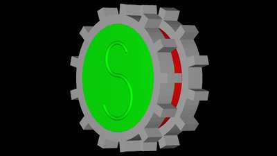
The rotor of a hybrid stepper motor is composed of an axially magnetized permanent magnet with soft iron gears attached to the poles. 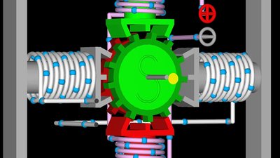
The command sequence is identically to that of a bipolar stepper motor (see table at the top of the page). Whenever a phase is enabled, the teeth representing a south pole at the rotor line up with the teeth of an electromagnet forming a magnetic north pole at the stator (bottom of the drawing). In contrast the gear at the back of this animation is connected to the north pole of the permanent magnet and its teeth line up with that electromagnet forming a south pole at the stator. 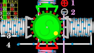
The front view illustrates the alignment of rotor and stator poles clearly. In total, the rotor in this drawing has 26 poles. With each full step the rotor moves by half the angle between two poles which is less than 7 degrees. 52 full steps are needed for a 360 degree turn of the motor shaft. With a half step, the motor spins less than 3.5 degrees, thus 104 half steps are needed for a full turn. <<< DC motor (wound stator) AC motor >>> News The Project Technology RoboSpatium Contribute Subject index Archives Download Responses Games Links Gadgets Contact Imprint |
||||||||||||||||||||||||||||||||||||||||||||||||||||||||||||||||||||||||||||||||||||||||||||||||||||||||||||||||||||||||||||||||||||||||||||||||||||||||||||||||||||||||
|
|