|
|
|
|
News The Project Technology RoboSpatium Contribute Subject index Download Responses Games Gadgets Contact <<< Demonstration servo motor Stationary engines >>> Adjustable jointsThe video about adjustable jointsConstruction and working principles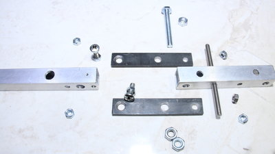
In this chapter, I would like to introduce you to a few joints that are fairly easy to manufacture, but extremely robust and with low backlash. Common to all constructions is the fact that the joints are designed to be adjustable, which can compensate for minor inaccuracies during manufacture. The core elements are screws with round heads and flat iron bars with countersunk holes - both construction elements are each attached to an aluminum square tube. 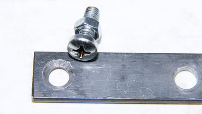
The holes in the flat bars are smaller than the diameter of the screw heads - I used 8mm drills for the 6mm screws shown here. I then countersunk these holes with a 12mm drill, which corresponds to the diameter of the screw heads. The contact area between the screw head and the socket in the iron bar is more precisely defined by the central hole, which reduces backlash of the joint. 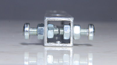
Two 6mm screws are screwed to the one aluminum square tube with a total of 4 nuts. 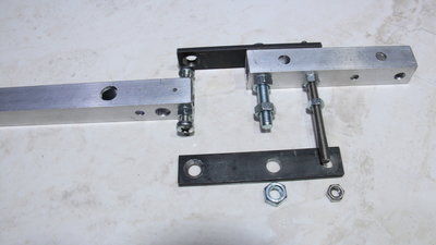
One of the two flat bars is attached to the second square tube with two pieces of threaded rods. 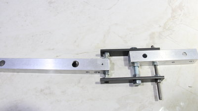
The second flat iron is now also screwed on and pressed with the nuts on the screw heads so that the desired stiffness of the joint is achieved. Here the joint is adjusted in such a way that the two aluminum square tubes are not in line - it's another parameter that can be varied with this design. 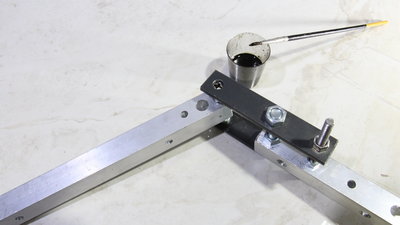
The contact area of the round screw heads with the countersunk holes is very small, which causes noticeable wear during the first movements, so the joint may need to be readjusted after the first operation. A drop of used engine oil ensures that the joint moves smoothly - the second advantage of the central hole is that the lubricant can be applied easily. This very simple construction has really extremely low backlash and wear is negligible if you lubricate with a drop of oil every now and then. 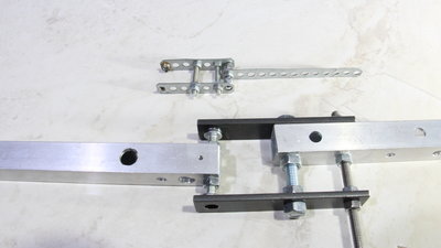
Another advantage is that you can adapt this joint principle to a wide variety of application scenarios: If 4mm screws are used as shown here, the dimensions shrink, which is an advantage for small machines. 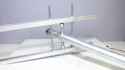
If high forces are to be absorbed in large projects, larger screws can be used - here you can see a piece of 10mm thread. Cap nuts act as rod ends - with their hemispherical, smooth surfaces, they are a good choice for this type of joint. In addition to the dimensions, this joint type is also suitable for experimenting with different materials: Iron on iron is a very unfavorable combination of materials without lubrication. Iron on aluminum, on the other hand, runs significantly more smoothly even without oil. 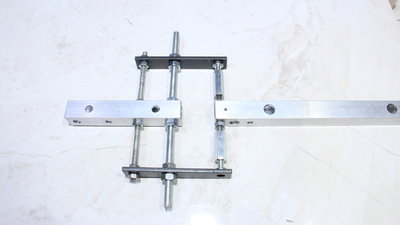
In addition to the screw size, the distance between the flat bars is a parameter for experiments: If the distance is increased, the forces acting on the joint socket and the screw heads decrease under load perpendicular to the pivot axis due to the physical laws. 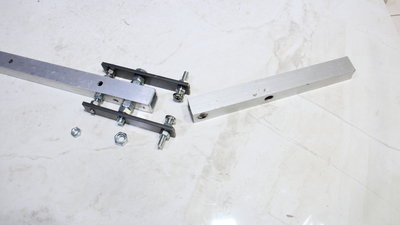
Here is another variation of the joint type: The screws are connected to the flat bars and the screw heads rotate in holes in the aluminum square tube. 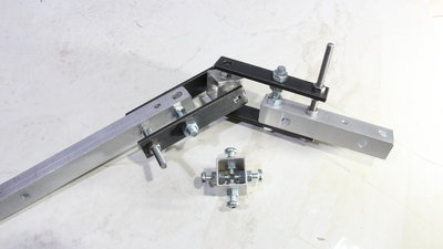
If a universal joint is required that can rotate around 2 axes, this is also not a problem: The center part consists of four screws, attached to a small piece of square tube. Both axes are adjustable, the universal joint is sturdy and has very little backlash. 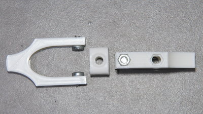
I turned on my 3D printer for the next experiments: The material combination is now steel and plastic, more precisely PLA - that works very well even without lubrication. The centerpiece is a cube with 4 "dents", serving as the sockets for the screw heads. Here, too, "holes" go through the cube in order to keep the contact area between the screw head and the cube smaller and therefore more precisely defined, which reduces the backlash of the joint. 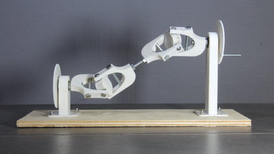
Two universal joints form a Cardan shaft and can compensate for the axial misalignment on drives. 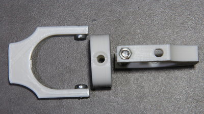
If a higher torque is to be transmitted, screws with larger heads do not necessarily have to be used: It is sufficient to enlarge the dimensions of the joint forks and the center piece - thanks to the law of the lever. DownloadYou can get the 3D files of the joints as download pakage.<<< Demonstration servo motor Stationary engines >>> News The Project Technology RoboSpatium Contribute Subject index Archives Download Responses Games Links Gadgets Contact Imprint |
|
|