|
|
|
|
News The Project Technology RoboSpatium Contribute Subject index Download Responses Games Gadgets Contact <<< Encoder disc (2) Computer mice >>> Transmissive optical sensorsThe video about transmissive optical sensorsNote!In this chapter I am describing, how to figure out the pin configuration of unknown transmissive optical sensors. The methods shown here result in an operation of the sensors far from the optimum!. It's always better to search for the accordant datasheet and calculate your circuit design using the given parameters (e.g. LED current).Unknown pin configuration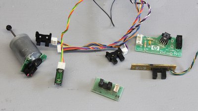
Old printers or scanners are a good source for transmissive optical sensors. The devices shown here are from an all-in-one printer (HP OfficeJet Pro 8500 Wireless) Transmissive optical sensor with 4 pins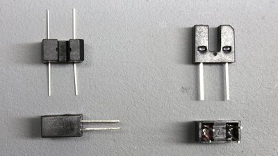
Usually, Transmissive optical sensor have four pins. On one side there is an LED, typically emitting infrared light and on the opposite side there is a light sensitive transistor. 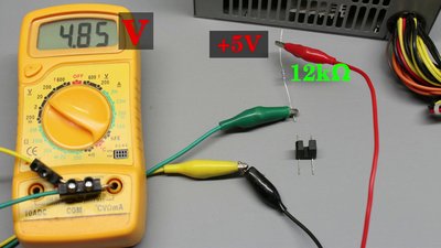
To determine the pin configuration, a 5V DC power supply, a multimeter dialed to voltage measurement and a resistor with a value somewhere around 10 kiloohms is needed. The voltage across the pins is recorded while the optical sensor gets connected to the DC voltage through the series resistor. We get four variations of the pin configuration, by what we can read nearly 5V at three of them and finally one configuration with a clearly lower voltage drop. That's the LED side of the device in forward configuration. 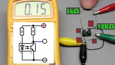
Next thing to be done is figuring out the polarity of the receiver side. We need a second resistor also having a value of approximately 10 kiloohms. That series resistor is connected to the phototransistor as well as to +5V. With the multimeter, the voltage across the photo transistor is detected. As soon as the LED side gets also connected to the voltage source with forward polarity, the reading on the multimeter should drop clearly. If (nearly) nothing happens, the polarity on the receiver side has to be swapped. With the LED turned "ON", the voltage across the receiver should drop clearly below 0.5V. Lower the value of the series resistor on the LED side until you get a reading of 0.15V with a 1 kiloohms resistor at this special device. With the 12 killoohms resistor on the receiver side and the 1 kiloohms resistor on the LED side, the device shown in this picture can be operated at a 5V DC power source. The LED current adjusted with this instruction is usually far from it's limit. For better switching speeds you can usually halve the resistance value, but keep in mind that you should never exceed the current limit of the LED or else you will destroy your sensor immediately! Transmissive optical sensor with 3 pins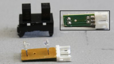
In an old printer I found several optical sensors having just three terminals. At the bottom of this device you can clearly see that ground pin of the LED side is joined with the transistor side. If that path is hidden, you can dial your multimeter to continuity measurement to determine, what pins of the LED and receiver side are joined. 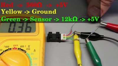
We can identify the configuration of the terminals using the same method as above: Connect the optical sensor to the 5V Line through the 12 kiloohms series resistor using all combinations possible while recording the voltage across the terminals of the device. Once again there is only one configuration with the LED being forward biased and so a voltage reading clearly below 5V. With that, the ground pin and the LED side are identified. The third terminal is joined with the second pin of the receiver side. The polarity of the receiver side is obvious - as can be seen on the photo, the joined pins are connected to ground. Now, the photo transistor is connected to +5V through a 12 kiloohms resistor while the resistance value at the LED side is lowered until we get a reading of less than 0.5V across the receiver. That's a save configuration for this sensor type at 5V supply voltage. Rotary encoders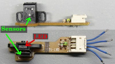
Using two transmissive optical sensors, you can build a rotary encoder, as demonstrated in the previous chapter. Printers and scanners usually use rotary encoders, having two receivers in one housing thus they are very likely sources for that type of sensors. The receiver side can be easily distinguished from the LED side since only one LED is used to illuminate both receivers, thus the two pins are running to the light emitting diode. 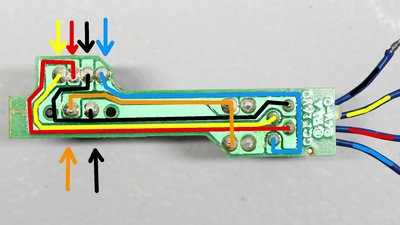
Usually the sensor unit is soldered on a tiny extra board with just a few tracks on it that are easy to follow from the plug to the sensor, thus you can guess the pin layout (this is from a Canon IP4200): The pins of the sensor outputs are joined directly with the plug - there are no branches nor are additional components soldered on their paths (Yellow + Blue). Ground of LED and receiver are usually joined (Black). The remaining terminal is for the positive supply voltage: It's running directly to the receiver side (Red) and to the LED through a series resistor (Orange). The sensor units are usually operated at 5V, but you should try 3.3V first to do it the safe way. If you don't get clear signals close to 3.3V when blocked and close to 0V with the metal sheet removed, try 5V. If you need 5V in your application at all costs, you can try 5V even after a successful test at 3.3V. Be warned that a too high voltage will destroy your sensor unit immediately! 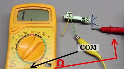
If there is no clear view on the tracks of the board, you can record the resistance between LED pins and plug: Connect the "common" terminal of your multimeter with the pins of the LED during measurements, the red probe runs to the Ohm input. The lowest values recorded are the tracks running to the cathode and anode of the LED. The cathode is usually joined directly with ground of the supply voltage, the reading will be very close to zero ohms. The minimal reading of the second path is typically below 1 kiloohm which is caused by the series resistor between plus of the supply voltage and anode of the LED. The cables left are those of the sensor outputs. As often, a wrong wiring of your sensor unit will destroy that device immediately! So be careful and start testing with 3.3V. 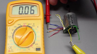
Another sensor unit I found in a printer is mounted on the rear of a DC motor: The drilled yellow and white pair of cables is very likely joined with the terminals of the motor. You can check that out by using a multimeter dialed to resistance measurement (you'll read nearly zero resistance). The remaining four cables are tested as done before using a multimeter with the LED pins as reference points. We get a minimal resistance of almost zero ohms for the purple cable (=ground) and 100 Ohms for the red cable that is very likely designed to be connected to the positive supply voltage. At 3.3V the sensor unit works fine. 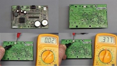
This sensor was at the carriage of the printhead (HP OfficeJet Pro 8500 Wireless). Not only because of the ink on the board, you can't follow the tracks. Furthermore there is no plug directly connected to the sensor, thus the measurements are done between the pins of the sensor: The test lead running to "COM" of the multimeter (black) is connected to the LED pins during measurements. Once more there is an alost zero ohms path (=ground) and one with a resistance lower than 1kΩ (=anode). I did not get stable readings, the display jumped between 100Ω and 1kΩ, which is caused by all the additional components (e.g. capacitors) soldered on the board. 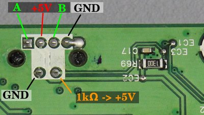
The resulting pin out configuration: When desoldering the sensor unit, it will very likely get destroyed (as mine did). If you don't need the whole board, cut out the sensor unit. After that you'll need a series resitor for the LED side. As explained above, start with a series resitor of around 10kΩ on the LED side and lower that value until you get a reading of less than 0.5V at the sensor outputs (A + B). 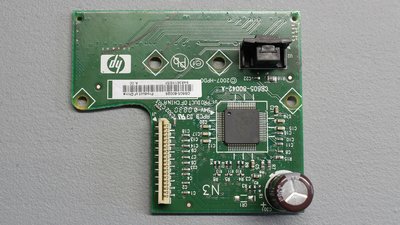
Another sensor from a printhead carriage (HP DeskJet F4210): 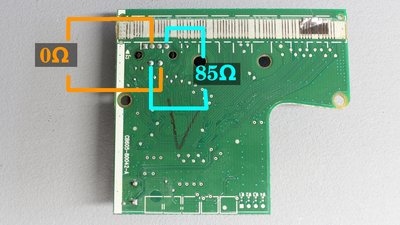
Note the varying pin layout!!! The path with the lowest resistance is not connected to ground, but to +5V! The series resistor of the LED is connected to the cathode. Good luck, that some of the devices on the board buffered the wrong polarity and heated up significantly before the sensor was destroyed... 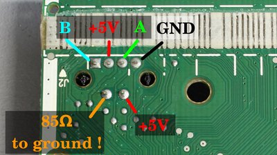
After swapping the polarity (connect the device as shown in this figure), the sensor still works. 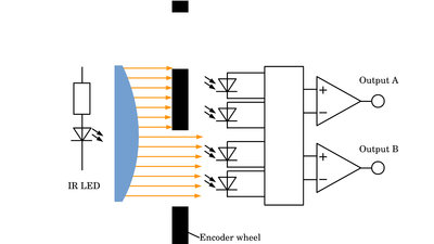
Please note! These sensors often only work with a very fine line pattern! So be sure to test your sensor with the original encoder disk or the plastic strip. The reason is the internal logic: Outputs A and B are connected to comparators having two optical sensors each. The outputs are only switched correctly when two edges of two lines run more or less simultaneously over the optical sensors of the two outputs while one output is always completely darkened and the other is then fully exposed. With wider encoder patterns there is no clear signal from the encoder. <<< Encoder disc (2) Computer mice >>> News The Project Technology RoboSpatium Contribute Subject index Archives Download Responses Games Links Gadgets Contact Imprint |
|
|