|
|
|
|
News The Project Technology RoboSpatium Contribute Subject index Download Responses Games Gadgets Contact <<< My computer history WM8650 >>> Arduino UnoThe video about the Arduino UnoGeneral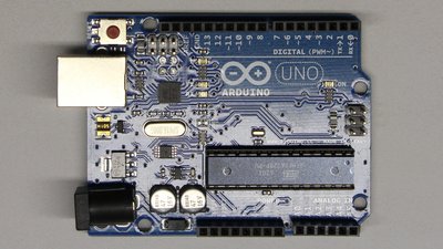
The Arduino Uno is a microcontroller board with an ATmega 328P chip. This microcontroller runs with a clock speed of 16MHz, it has 32 Kilobytes of program memory, 2 Kilobytes of SRAM and one Kilobyte of permanent memory. The USB interface of the Arduino board can be used to program the microcontroller and to exchange data with other computers. The ATmega 328P has 20 programmable input/output pins. 6 of those pins can be used as analog inputs. Another 6 of those pins can be used to generate pulse-width signals. The Arduino can sense the environment by receiving input signals and affect its surrounding by controlling peripherals like lights, servos or motors. The board can be supplied with electric power through the USB interface (5V) or through a second connector pin (6 - 20v). The Arduino software is published as open source tools, available for extension by experienced programmers and the hardware plans are published under a Creative Commons license. The integrated development environment is based on Java, hence it runs on various operating systems and allows users to write programs for Arduino using C or C++. The IDE comes with a software library called "Wiring", which makes coding of input/output operations very easy. Advantages+ Low energy consumption.+ Fast boot. + Large community. + Documentation available in many languages. + Simple programming thanks to available libraries. + Great extension board for computers with an USB interface (physical computing). Keyboard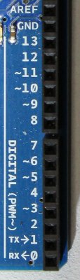 There is no connector for a conventional keyboard or a computer screen, thus the 20 input/output pins have to be used to interact with humans. A keyboard consists of multiple keys, which are nothing but push buttons whose state can be read through input pins. A voltage of 5V is correlated to the "open" state (HIGH signal) of the switch, while 0V at an input pin indicate the state "closed" (LOW signal). A pull-up resistor is used to get 5V whenever the switch is opened.
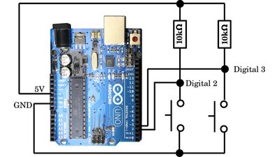
Screen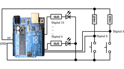
Some LEDs can act as "computer screen". Pushing a button can trigger an event, which is indicated by the LEDs. Variables can be displayed as binary numbers. A Liquid Crystal Display is more comfortable to read. The Hitachi HD44780 is a very common LCD for an Arduino board, using two lines of 16 characters. The contrast of the Display is adjusted by the potentiometer. No characters appear at the display whenever that contrast is adjusted too high or too low. 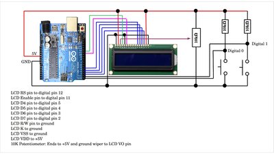
Source code counter with LCD for Arduino Uno Microcontroller Sensor disk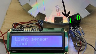
A toothed disk in conjunction with two optical sensors can be used as rotational sensor. The receivers of the optical sensors are connected to digital inputs 0 and 1. The LCD is connected as described above. 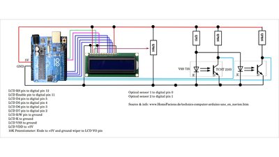
Source code optical sensor disk with LCD for Arduino Uno Microcontroller PID controllerIn the chapter about servos I have demonstrated a device made of a wiper motor. The precision of the homebuilt servo can be improved clearly with a microcontroller. A PID controller is implemented by software. PID means proportional-integral-derivative controller.The voltage forwarded to the servo motor by a proportional controller is increased by pulse-width modulation, the larger the divergence between setpoint and actual value. There is a linear correlation between the difference of both input values and the voltage forwarded to the motor:
U - Motor voltage (RMS value when using pulse-width modulation). KP - proportional gain. e - error (voltage setpoint minus voltage servo sensor) The difference between setpoint (voltage defining the setpoint) and actual voltage (voltage caused by the servo potentiometer) is named error value. 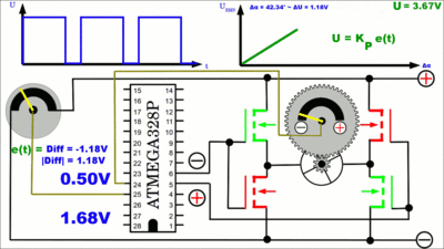
in turn, if the sensor reading approaches the setpoint, the rotation of the servo motor is slowed down. 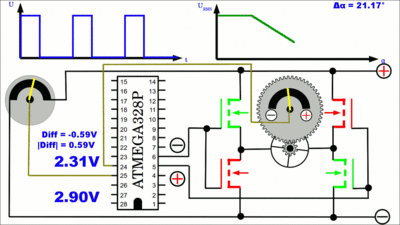
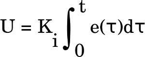
When using an integral controller, the voltage is raised, the longer the actual value differs from the setpoint:
U - Motor voltage (RMS value when using pulse-width modulation). Ki - proportional gain. e - error. 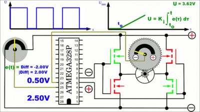
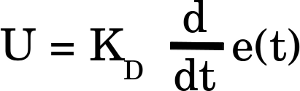
The derivative controller error is calculated by determining the slope of the error over time and multiplying this rate of change by the derivative gain KD. The motor is rotating faster, the higher the slope of error:
U - Motor voltage (RMS value when using pulse-width modulation). KD - proportional gain. e - error. 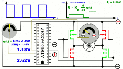
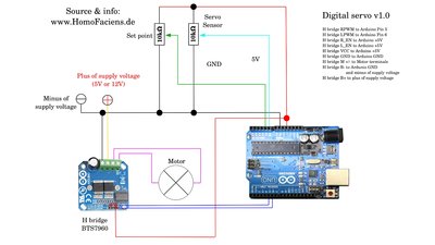
Using a pure derivative control unit, the servo motor stops rotating as soon as the setpoint doesn't change any longer, thus as soon as the potentiometer defining that setpoint stops rotating. In order to make the servo horn follow the adjustment of the input voltage exactly, proportional or integral parameters have also to be considered by the software of the control loop. ServoA combination of a proportional, integral and derivative control circuit is named PID controller. By software I have added a softstart mode and an emergency stop of the servo whenever a deadlock of the lever is detected.At the first test run, set MAX_DUTYCYCLE of the software to 75 in order to lower the maximum torque in case something goes wrong. When connecting the servo to the microcontroller for the first time, you have to consider the rotational direction of your wiper motor! Adjust the potentiometer defining the setpoint to the center position. If the servo moves to neutral position, too after connecting the circuit to the supply voltage, the polarity of the servo sensor is correct. If the wiper motor starts spinning away from the center position, the polarity of the servo sensor (+ and - connector) has to be swapped. The maximum current of the power transistors used in the circuit below is 13 A. If a current of 4 to 5A is running through your wiper motor in idle mode, it is very likely, that it is close to the maximum of the circuit under load. There are commercial H bridges available for the Adruino platform designed for clearly higher currents. Additionally those circuits are protected against overtemperature, overvoltage, undervoltage, overcurrent and short circuit. If you are not skilled in soldering electronics, those commercial products are a good investment. 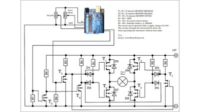
Source code wiper servo for Arduino Uno microcontroller This is my (non perfect) solution of attaching the potentiometer to the wiper motor: 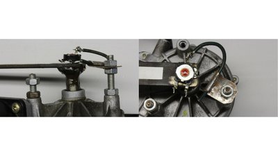
After many requests, this is a circuit layout using a BTS7960 H bridge for currents up to 42A. The modified sketch is part of the Download package. Digital linear servoA toothed disk scanned by two optical sensors can be used as rotational sensor instead of using a potentiometer. I have created a linear servo using that principle: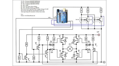
Source code linear servo for Arduino Uno microcontroller <<< My computer history WM8650 >>> News The Project Technology RoboSpatium Contribute Subject index Archives Download Responses Games Links Gadgets Contact Imprint |
|
|