|
|
|
|
News The Project Technology RoboSpatium Contribute Subject index Download Responses Games Gadgets Contact <<< PICO Servo CNC maschines >>> Automatic XylophoneVideo about the automatic XylophoneAbout the Xylophone
The musical instrument used for the conversion to an automatic xylophone is from the "cheap" category. I bought this on eBay. I bought a version with 25 metal plates so that I could at least make a little bit of "real" music. Parts listWhen buying components via the affiliate partner links I have listed in the table (or through the banners on my pages) you help to keep my my projects going without extra costs for you - many thanks!Clicking on the links does not mean you have to buy - you can simply browse through the pages ;-) Of course, supporting my freely accessible educational platform without shopping but by making a donation or becoming a Patreon also works. Many thanks to everyone who already sent me an obol!
Conversion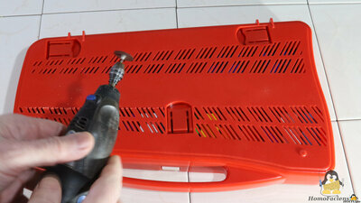
The first step in the conversion process was to make openings on the underside of the case. This can be done with a sharp knife and a ruler or a metal bar, but faster with a suitable power tool. 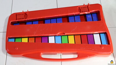
As you can see from the result, I'm not a gifted craftsman, but it doesn't matter, the scratched side is on the bottom and therefore normally not visible. 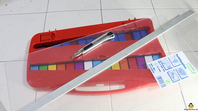
Then I cut covers for the openings from acrylic glass - this works best with a knife and ruler. 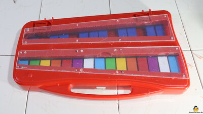
To mount these, holes are drilled in the housing and the covers. You should make sure that there is also space on the top at the positions for the holes - I didn't really take that into account with some drillings. It doesn't matter, it's just the underside. 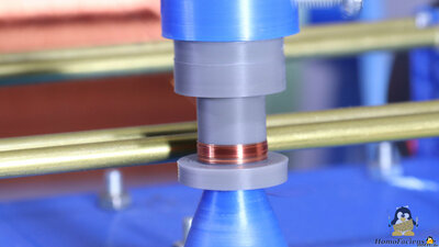
For the total of 25 electromagnets I made the corresponding core elements with the help of a 3D printer. In order to automate the winding process of the copper wire, I have converted a 3D printer into a winding machine 600 windings with a wire diameter of 0.1mm are wound on each electromagnet. 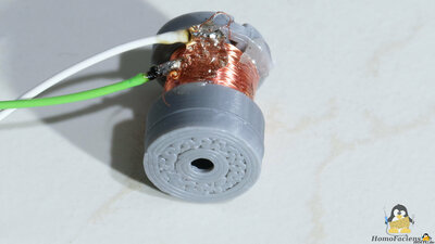
I soldered stronger wires to the thin wires of the coils and fixed them to the electromagnets with hot glue. 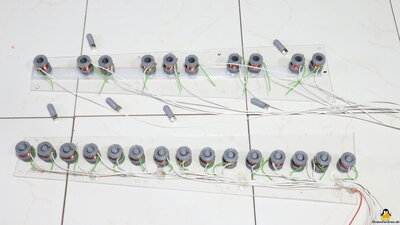
The electromagnets including the cables are glued to the Plexiglas covers. One coil end is soldered to the bare copper wire that leads to the positive supply voltage - here the green wires. The white wires lead to the control board. 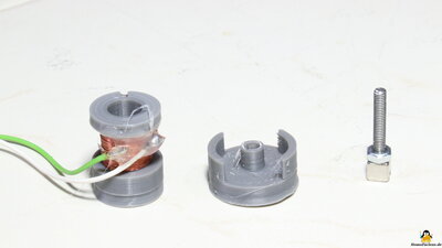
Permanent magnets are used as beaters, onto which a piece of a 3mm threaded rod with a suitable nut is glued. The threaded rod must be made of non-ferromagnetic material such as brass or, as shown here, stainless steel, otherwise the beater will stick to the metal plates of the xylophone. I use cube-shaped magnets with an edge length of 5mm. It is important to ensure that the magnetization runs in the direction of the glued-on threaded rod - the same magnetic pole should also always point upwards. If you have glued on the first magnet and checked whether it is pulled up by the electromagnet as desired, this serves as a template: The next magnet to be glued is simply snapped to the beater and marked on the underside. Then glue on the top. If a coil has been soldered with the wrong polarity, the magnet of the beater in question can be glued to the previously marked side. 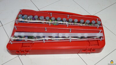
Bottom view of the converted xylophone. The plates are attached using 16mm long M3 screws. The back row of electromagnets (here at the front of the picture) is glued to 3D printed spacers because the purple metal plates are attached higher. 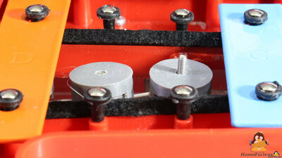
A guide on top of the electromagnet ensures that the beaters do not tilt. Electronics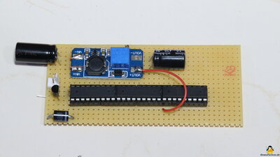
The coils are controlled via ULN2803 chips, which amplify the signals from the GPIOs of the Arduino Mega. Since 8 electromagnets can be driven per chip, but a total of 25 channels is required, I use a small-signal MOSFET to drive the remaining 25th coil. A step-up converter is used to boost the coil voltage up to 30V, which increases the strength of the tone. 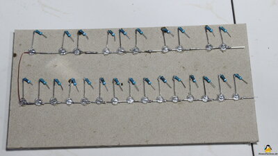
To indicate which note is being played, I attached a display panel with 25 LEDs to the lid of the xylophone. The LEDs are controlled by another 25 GPIOs of the Arduino MEGA. You could also switch the LEDs in parallel to the coils - but since these are only activated shortly, separate control pins makes sense. 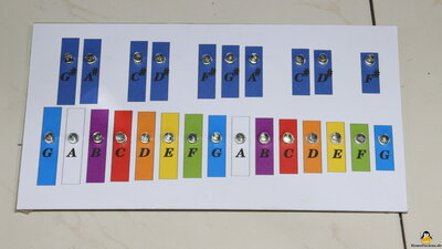
The LEDs light up as long as the corresponding tone is to be played - so songs can be learned and replayed. 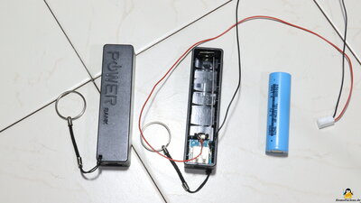
A power bank with a single 18650 battery cell serves as the power supply. The step-up converter is powered directly from this battery cell. Two cables are soldered to the terminals of the poles (not to the battery!). A step-up converter for the 5V output voltage is already installed in power banks. Switching a second step-up converter "in series" to this 5V output does not work - the two converters interfere with each other and as a result neither of them reaches the specified output voltage. 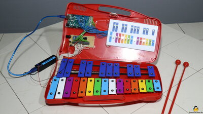
The 5V output powers the Arduino MEGA. Thus, the xylophone switches off as soon as the battery cell is discharged. 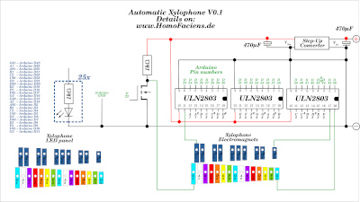
Circuit diagram DownloadThe Download-Package (4.6MB) includes the source code, the circuit diagram, as well as the 3D files.<<< PICO Servo CNC maschines >>> News The Project Technology RoboSpatium Contribute Subject index Archives Download Responses Games Links Gadgets Contact Imprint |
|
|