|
|
|
|
News The Project Technology RoboSpatium Contribute Subject index Download Responses Games Gadgets Contact CNC V3.1 - Linear drives and DIY printerThe video about CNC v3.1 (printer)Linear drive of an printer head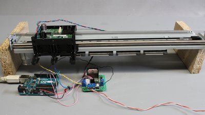
This linear drive is from an old printer (HP DeskJet F4210). The optical sensor (see pinout) is connected to two input pins (pin 2 and 3) of the Arduino Uno, the DC motor is controlled through an H bridge (Typ L298N) being connected to pin 5 and 6 of the microcontroller. 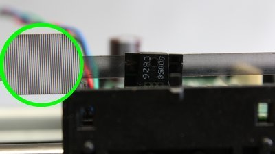
Thin lines are printed on the plastics stripe that are scanned by an optical sensor. The working principle is described in detail in the chapter about rotary encoders and transmissive optical sensors. With the linear sensor, the microcontroller can detect movement relative to the plastics stripe. If the carriage is stopped by hand, the motor is kept energized until the mechanism is released and the setpoint is reached. When deflecting the carriage manually, the microcontroller compensates the movement of the print head caused by the side load. In doing so, backlash or slip are partially balanced by the control loop. The microcontroller detects movement in relation to the line pattern on the sensor stripe. When removing the tab from the mechanics, the carriage is controlled in such a way, that the print head follows the movement of the plastics stripe. Ensure that the sensor stripe is mounted tightly which is done by a spring steel plate at this mechanics. Linear movement with threads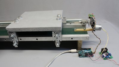
Spindles are often used to transform rotational movement into linear movement. Here, a 6mm threaded rod is used. Whenever the tread is turned by the motor the carriage moves along the aluminum square tubes, guided by ball bearings. Ball bearings are used to reduce friction. The working principle is described in detail in the chapter about rotational encoders. 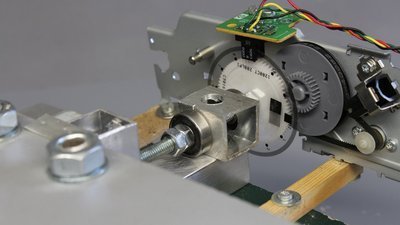
Geared motors can be used to turn the spindle (direct drives usually don't have enough torque). The brushed DC motor shown here is from an old printer and the gear ratio of the plastics wheels is 12:1. The sensor disc from the printer, mounted at the plastic gear on the treaded rod, is scanned by two transmissive optical sensors. The fine line pattern on the sensor disc results in 3000 pulses per revolution. With the given pitch of 1mm per turn, the tread transforms one step into a linear movement of 0.3 micrometers - at least in theory. In practice, backlash is usually higher than the academical step width. The microcontroller can't detect the backlash, thus it can't compensate that kind of movement. Another drawback of that fine line pattern is the large number of pulses generated by the optical sensors with each revolution which limits the rotational speed - remember the low clock speed of the microcontroller. 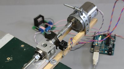
With two transmissive sensors and a toothed sensor disc having 4 teeth, we get 16 steps per revolution. With each step the carriage moves 0.06mm - a resolution that is sufficient for many applications. The DC motor used here has a transmission of 50:1. 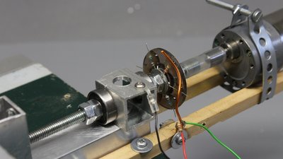
We can also use the rotational sensor composed of resistors in the control circuit. Instead of using a second wiper, the washer side of the sensor is pulled to ground through the ball bearings whose resistance is obviously low enough. Contact bounce is a huge drawback of this type of electromechanical encoder limiting the maximum revolution speed, 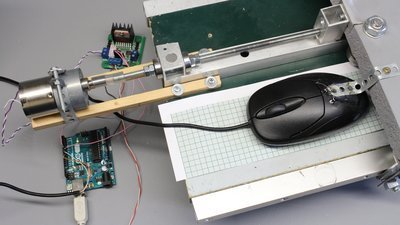
In principle, an optical mouse can be used to sense the motion of a linear drive. Only the change in movement along the Y axis is processed by the microcontroller. 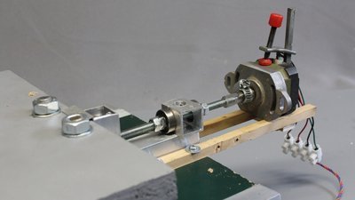
When connecting a bipolar stepper motor to the threaded rod, the linear drive works even without sensor feedback. When using a linear drive without feedback loop, the torque generated by the stepper motor must be sufficiently high, so that the movement of the mechanism isn't interrupted unforseen. DIY printer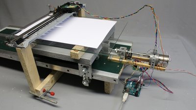
The printhead drive is mounted perpendicularly to the linear drive composed of a DC motor and a threaded rod. 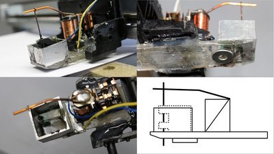
A relay with a tiny lever moves a wire up and down, transferring ink from the reservoir to an underlaying sheet of paper. The washer at the bottom of the print head slides along the paper, preventing the printhead from smearing the ink. I am using exterior house paint (don't know the correct word for it), which is sufficiently viscid. Create a removable linkage for the print head or else it is difficult to clean the ink reservoir after a print job... 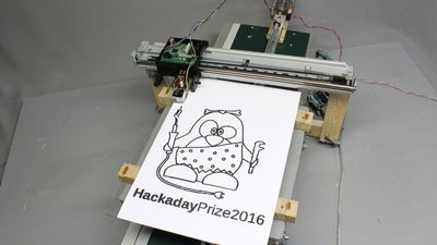
The working principle is similar to that of dot matrix printers. With no more than one needle, it is inevitably a monochrome printer, producing large dots with low speed. Nonetheless that's why this machine is an illustrative way of explaining how printers work or how bitmap graphics are drawn on a computer screen. Each dot has a diameter of approximately 1mm, thus the resulting resolution is 25 dots per inch. Around one hour passed by until the 300 times 318 pixel graphic, resulting in 11000 black dots was transferred to the paper sheet. Parts list
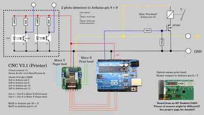
Schematics and software of the printer as well as the linear drives of this chapter are available as download package. News The Project Technology RoboSpatium Contribute Subject index Archives Download Responses Games Links Gadgets Contact Imprint |
|
|