|
|
|
|
News The Project Technology RoboSpatium Contribute Subject index Download Responses Games Gadgets Contact <<< CNC v3.x series CNC v3.1 (Printer) >>> CNC V3.0The video about CNC v3.0Parts list
Build instruction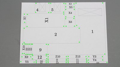
I glued the templates on the cardboard using only glue spots at the corner points of all parts (green marks). In doing so you can easily remove the paper templates after cutting all parts. Furthermore the paper as well as the cardboard swell when glued at the whole area. 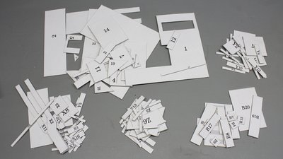
All parts were cut using a sharp knife and a metal bar as guide. 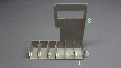
You can build the base box with the LCD on the right... 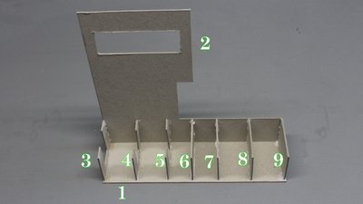
...or on the left side - as I did in the video. 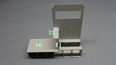

X axis: Part X12 must fit between X4 and X6. 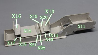
Use some cardboard as spacer when gluing X19 and X22 (and move it while the glue dries to avoid it from being glued, too). 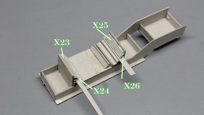
Same is for gluing X23 to X26. 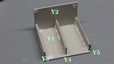
Y axis. 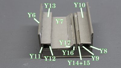
Another cardboard spacer is used when gluing Y14+15 and Y16... 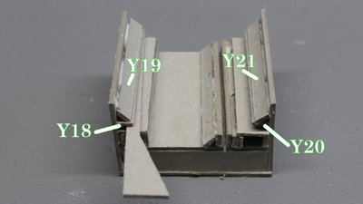
...and Y18 as well as Y20. 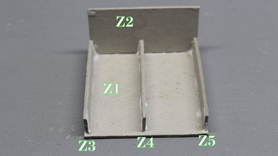
The carriage for the Z axis is build in the same way. Z6 is glued vis à vis to Z2 after gluing Z7 (see picture below). 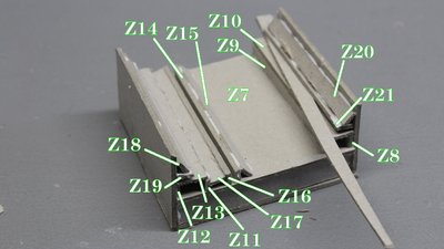
Cardboard spacers ensure the right gap at the guiding slots. 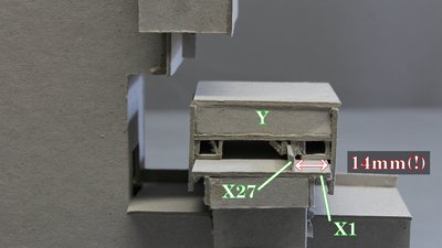
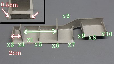
In theory, the distance from the edge of X1 to X27 is 14mm. However there are tolerances when working with cardboard, thus hold the Y carriage in place and measure the distance needed at your build. There must be a gap on both edges of the Y carriage. 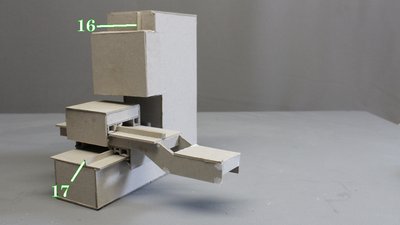
Same is for gluing 16 and 17. 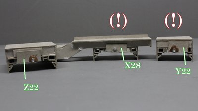
The M3 nuts are best glued using some epoxy. Wood glue worked for me, too, but it needs hours to dry. Attention! X28 and Y22 have to be glued on the back side of this picture when using the CNC with servo drives! 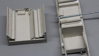
Enforce the mount with some cardboard. 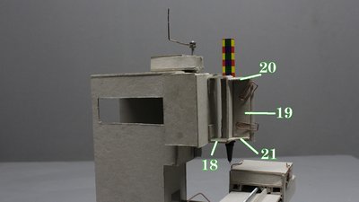
Pen holder. The ball pen is glued on a piece of cardboard using hotglue. That cardboard is linked with the pen holder using two paperclips. 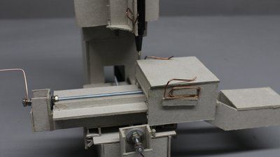
Use some cardboard to glue two paperclips to the Y carriage so that 5x5cm paper can be clamped to the CNC table. Manual operation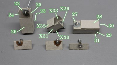
Mount points of the cranks. 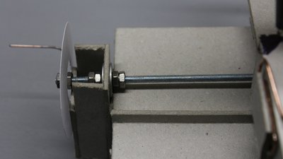
Six nuts and two washers are needed to keep the threaded rod and the crank in place. Cut lengths of the threaded rods: X=120mm Y=140mm and Z=100mm. 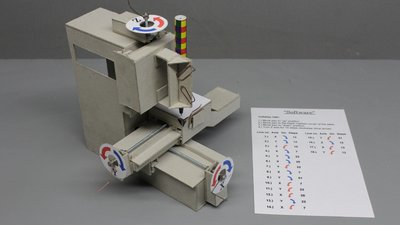
The "software" is a set of instructions printed on a sheet of paper. A single instruction consits of the axis as well as the direction and the number of turns and you must process all commands in sequence. Your brain becomes the microcontroller and your hands are used as stepper motors. This is a very demonstrative way of teaching computerized numerical control. Electronics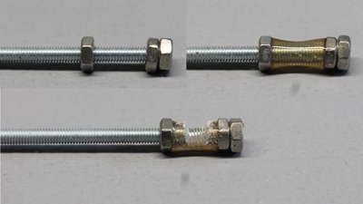
10mm of the threaded bars are covered with epoxy at one end. That insulating layer is grinded down to the blank metal at one point. Cut lengths of the threaded rods: X=120mm Y=140mm and Z=100mm. 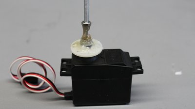
That end of the threaded bars is glued on the servo levers. I am using hotglue to get a flexible mount - remember that you won't get a perfectly centered linkage. 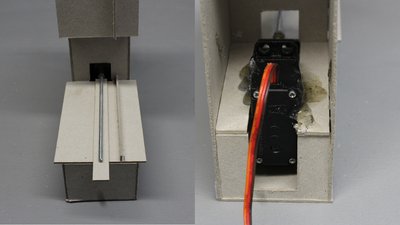
Align the threaded bars in parallel to the guides when gluing the servos (I am using hotglue). 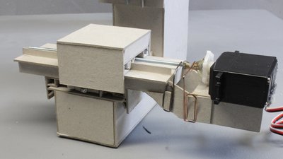
Rotary switches composed of paperclips are used as sensors. 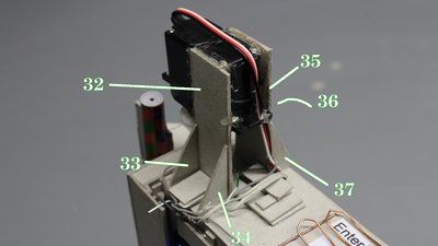
Servo driving the Z axis. 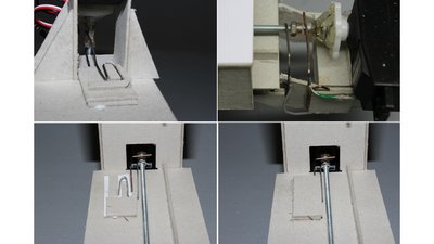
Use an insulating layer of paper when arranging paperclips on top of each other. 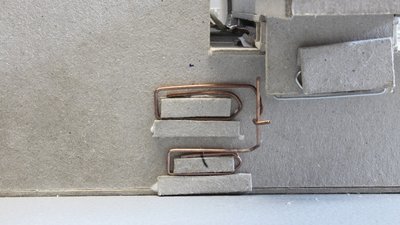
Two more paperclips are needed for each end switch. 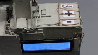
Three push buttons made of paperclips are used to control the machine. 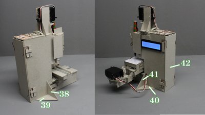
Parts 38 to 41 give the machine a stable stand. The back cover is kept in place by four paperclips. 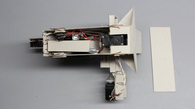
Arduino and batteries fits in the box. 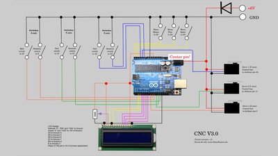
Circuit layout Battery box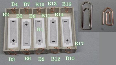
I have bend small paperclips from large ones. 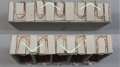
Two near by paperclips are joined. 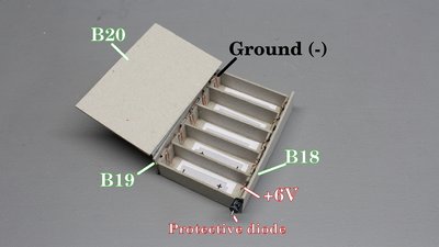
B18 to B20 are needed to insulate the battery box. SoftwareThe software can plot capital letters and digits. The data is in the source code, thus only computer experts will be able to create own graphics.You can control the servos stepwise in the main menu which is useful to detect errors or to assemble the machine. You can get the Arduino sketch as well as the templates and circuit layout in the column download. <<< CNC v3.x series CNC v3.1 (Printer) >>> News The Project Technology RoboSpatium Contribute Subject index Archives Download Responses Games Links Gadgets Contact Imprint |
||||||||||||||||||||||||||||||
|
|