|
|
|
|
News The Project Technology RoboSpatium Contribute Subject index Download Responses Games Gadgets Contact <<< Extruder V4.1; Auger screws Extruder V5.1 >>> Direct granules extruder V5.0: Prusa MK4The video converting a Prusa MK4 to a granule printer.Why a Prusa MK4?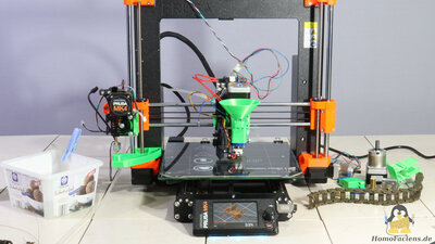
I chose the Prusa MK4 for several reasons: In addition to the mechanical qualities of the device, the open source philosophy of the manufacturer Prusa is a very important point: FFM printing is so widespread because this technology was developed free of patents and with open documentation by the community, which also applies to my granule extruder. 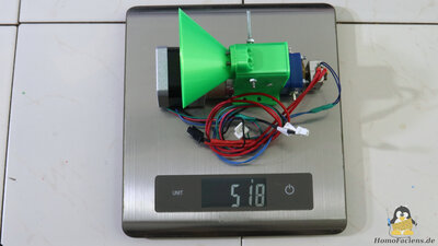
Let's have a look at the advantages of the MK4's hardware: Granule extruders are heavier than printheads for filament printing: The original print head of the MK4 weighs around 300g, while my granule extruder version 5.0 with a Nema 17 stepper motor and a 5:1 gearbox weighs a whopping 520g. 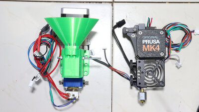
The heavy stepper motor including gearbox is at the top, the nozzle, where the molten plastic exits is at the bottom. Overall, the granule extruder is only a little longer than the original Prusa extruder - the mechanics of the MK4's X-axis are therefore designed for a similar construction. 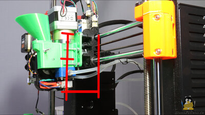
The belt for the drive along the X-axis should ideally run through the center of mass of the extruder, which is not quite the case at the moment. The long design of the extruder leads to long levers: The path from the attachment points to the nozzle tip is longer compared to the original print head. The fact that the X-axis of the MK4 has two rails is an advantage because the leverage forces are absorbed with less bend of the rods. The distance to the rods is larger not only along the extruder axis, but also in the direction of the Y axis - the nozzle should be as close as possible to the two rails. 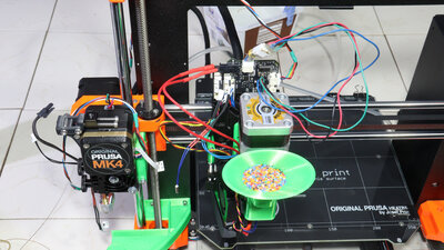
When it comes to electronics, the conversion is anything but final, too: The original print head is not located on the left of the X-axis so that it can be replaced quickly, but rather to use the integrated limit switch for the Z-axis. In the Prusa MK4, the height above the print bed is measured using a force sensor that registers a very slight bending of the mechanism as soon as the nozzle tip touches a surface. With this system, the build plte can be measured very precisely, which is definitely an advantage when printing the first layer - another reason why I chose the Prusa MK4. Since this sensor is integrated into the frame of the original extruder and I didn't want to saw it in half, I ordered corresponding sensors with different value ranges - let's see if I can use them. Since the currently improvised limit switch only measures the height on the far left of the X-axis, so far only prints with a rather small footprint can be made. Build instruction extruder tube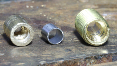
I designed Extruder V5.0 so that it can be rebuilt with the simplest tools possible, even if that currently means compromises in terms of print quality. I made the tube using my good old drill press - I showed how this can be done better with a lathe in a previous chapter of this series. 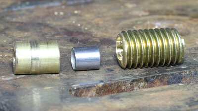
Wie zu sehen, sind die 3 Teile nicht perfekt geraten - Ziel von Version 5.0 ist es zu zeigen, was mit weniger präzise gefertigten Teilen machbar ist. 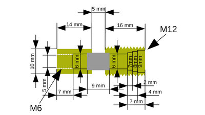
The upper part consists of an approximately 16mm long part of an M12 brass screw. As with the previous extruder V4.1, this part is drilled completely through with a 3mm drill and then with a 6mm drill. Then with a 7mm drill an approximately 2mm deep hole for the connection to the hotend is drilled and for the step bore at the top, followed by an 8mm and a 9mm drill. The hotend build starts with a 3mm hole that is widened with a 5mm drill and then an M6 thread is cut. From top, half of the hotend is then drilled in with a 6mm drill and about 2mm deep with a 7mm drill. An approximately 9mm long piece of stainless steel tube with an inner diameter of 6mm and an outer diameter of 7mm acts as a heat barrier. 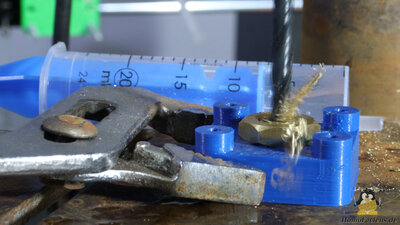
In order to center the hole, I printed appropriate holders for the brass parts. 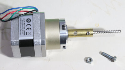
The linkage between the transmission output shaft and the screw is made of drilled round brass. Since my extruder principle requires a large gap between the extruder screw and the tube wall, the screw can rotate freely even if it is not perfectly centered in the stiff coupling. 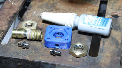
The central part of the water cooling is printed from PETG - nothing needs to be soldered here, as was the case with the previous model. The components are sealed with loctite. DownloadThe 3D files and the dimensional drawing of the extruder are available as download package.Sample printsFor all sample prints there is:Track link: Layer height: 0.2mm Nozzle: 0.4mm Print time: 17min Size: 27x25x12mm Material: Recycled PLA I deactivated the software refinements "pressure advance" and "input shaping" that the Prusa MK4 offers during the current tests. When it comes to printing tests, it's still important for me to see what the extruder can deliver, without interference from the printer firmware. 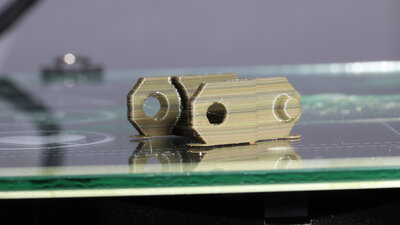
Print with 30mm/s. 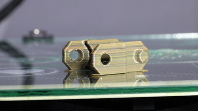
Print with 60mm/s. 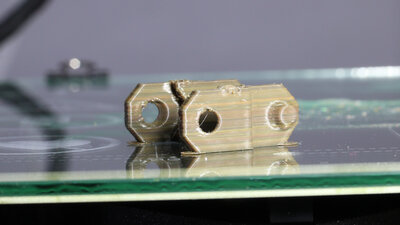
Print with 120mm/s. 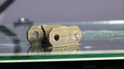
Print with 20mm/s. <<< Extruder V4.1; Auger screws Extruder V5.1 >>> News The Project Technology RoboSpatium Contribute Subject index Archives Download Responses Games Links Gadgets Contact Imprint |
|
|