|
|
|
|
News The Project Technology RoboSpatium Contribute Subject index Download Responses Games Gadgets Contact <<< SCT version 2 Switching LEDs >>> Microcontroller setThe video about the microcontroller starter kitGet the starter kit at Gearbest Content of the box1x Funduino-Board with ATmega 328P microcontroller and an USB interface1x Breadboard Jumper kables male/female 1x USB cabel 1x 9V battery adapter 1x Stepper motor + driver board 1x Micro servo 15x LEDs (5x Red, 5x Green, 5x Blue) 18x Resistors (8x 220Ω, 5x 1kΩ, 5x 10kΩ) 1x Potentiometer 1x RGB LED 1x 7-Segment display (single digit) 1x 7-Segment display (4 digits) 1x 8x8 LED matrix 1x 2x16 character LCD 1x Sound level sensor 1x Buzzer 1x Piezo speaker 1x IR remote control + IR receiver 1x Relay 10A 1x 8x8 Push button matrix 1x RFID scanner 2x RFID module (key chain + card) 1x Water level sensor 4x Push buttons 3x Light sensor 1x Shift register 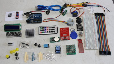
What's inside the box. Beispielschaltungen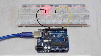
Physical Computing starts with a blinking LED. Note the correct polarity of the LED (short pin belongs to GND of the Funduino) as well as the correct resistance value (220&Omega); 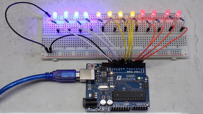
If you made one LED working on a microcotroller, you can simply scale up the circuit to multiple LEDs. 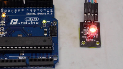
With three LEDs in one case, having the colors red, green and blue, you can mix nearly any color. 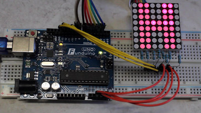
Multiple LEDs in a matrix can be used as a screen: The version shown here has 8x8, thus 64 red pixels in total. 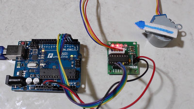
To control the stepper motor you need 4 outout pins. Depending on the switching sequence, the motor turns clockwise or counterclockwise. The frequency of the pulse sequence rules the speed of the motor. 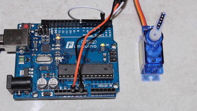
Servos are compact geared motors that can be controlled through a single output pin. The control signal is pulse width modulated having a frequency of 50Hz and a duty cycle ranging from 5 to 10 percent. With that, the servo lever can be commanded to any position ranging from 0 to 180 degrees. 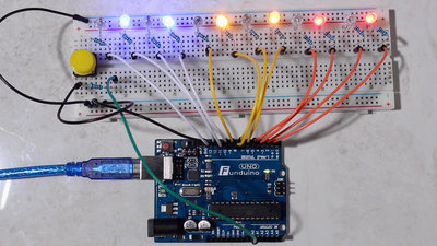
Giving the microcontroller input from it's environment makes computing even more interesting. The most simple input device is a push button. 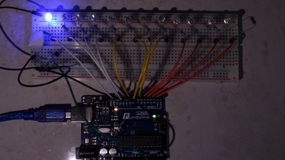
You can use a sensor instead of the push button - here it is a light sensisive device. Whenever light hits the sensor, the situation for the microcontroller is identical to pushing the button in the previous experiment. 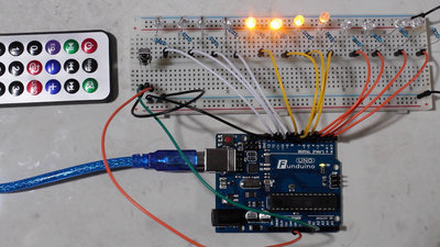
That principle even works with infrared light after changing the sensor. Those of you that are too lazy to create the pulse train manually can use a remote crontrol - there is also a microcontroller inside that box. 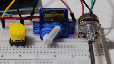
6 of the inputs can be used to convert an analog voltage into a digital number instead of detecting nothing but an ON or OFF state. Here, a potentiometer operates as voltage divider and so creates a voltage ranging from 0 to 5V at the GPIO of the microcontroller. With that, the angle of rotation can be detected and by software, you can command the servo lever syncroniously to the angle of the potentiometer. A simple push button triggers a different branch in the software by what the servo starts rotating into the opposite direction of the potentiometer. 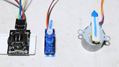
A joystick is made of two potentiometers, by what you can control the servo through horizontal movement of the stick and the stepper motor through vertical movement. This joystik has also a built in push button, so that you can swap the direction of movement by software. 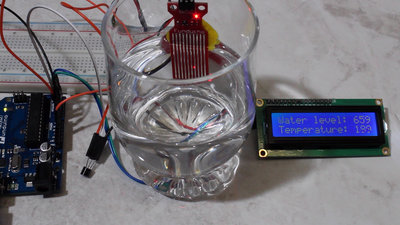
Instead of the LED matrix of a previous experiment, you can also use the 2 times 16 characters LCD that's in the box. With that you can display the readings on the analog inputs. Part of the kit is a water level sensor that detects the filling height in the water glas. A temperature sensor is connected to a second analog input. The sensor readings are displayed as raw value ranging from 0 to 1023. Calibration of both sensors is needed to get the conversion factor to temperature and water level. 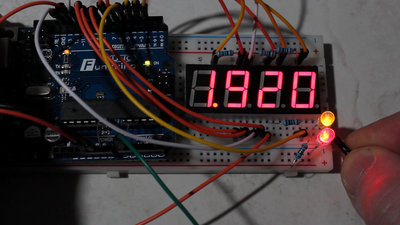
Numbers can be displayed with a 7 segment LED. Either using a single digit or using the module having four digits. It's all that's needed to create a simple voltmeter. Note that you will destroy your microcontroller if you connect that simple voltmeter to volatges different from 0 to +5V DC voltage! 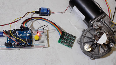
The current a GPIOs can deliver is limited, thus you can't drive powerful peripherals directly. Here, a relay is used to boost current and voltage for a wiper motor. To prevent the motor from being actuated by unautorized persons, access to the relay is not granted until the correct code is typed on a 4 times 4 pushbutton matrix. 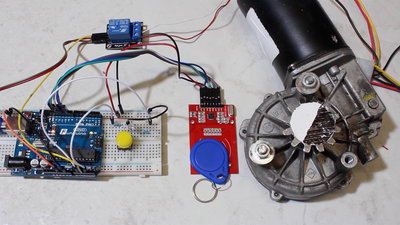
Unlocking the motor is done more comfortably through a Radio Frequency Identification key chain that is included in the kit. That chip sends the unlock code to the microcontroller as soon as it comes close to the scanner. 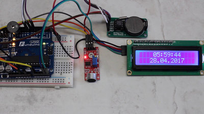
A real time clock module is also part of the starter kit. Time keeps ticking through the battery of the module even if the microcontroller is turned off or reset. With that, you can implement real time functionality. A simple clock turns into an alarm clock by connecting the buzzer to the board and with the sound level module you can turn off the alarm signal by voice. Example codeThe sample codes of the video are available in the column Download.You can find the wiring instructions in the source code. <<< SCT version 2 Switching LEDs >>> News The Project Technology RoboSpatium Contribute Subject index Archives Download Responses Games Links Gadgets Contact Imprint |
|
|