|
|
|
|
News The Project Technology RoboSpatium Contribute Subject index Download Responses Games Gadgets Contact <<< CNC v3.2.2 CNC 3018Pro Mostics >>> CNC engraver T8The video about CNC engraver T8Get this machine on Gearbest. Description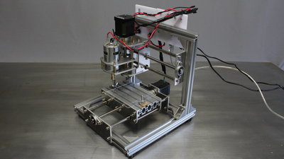
I got this CNC machine type T8 from the online shop Gearbest. The CNC is sold as engraving machine, simply because the mechanics is too weak to balance side load as occuring while carving wood or plastics with a milling bit. The machine is great to learn or teach base knowledge about Computer Aided Manufacturing (CAM). With the low price you don't burn much money when breaking a part because of an operating error (something that will happen sooner or later). There is a lot to learn and so a lot that can go wrong in the software chain from your 3D CAD model to the machine commands. It's a good device to see how things work in general. 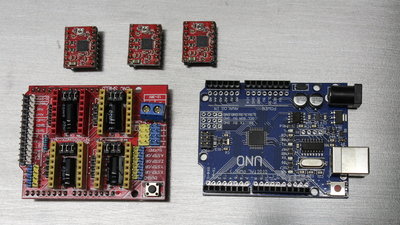
All three axes are driven by bipolar stepper motors through spindles. The electronic board is an Arduino Uno clone with a CNC shield. The firmware running on the microcontroller is grbl, thus the machine can process G-code. 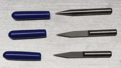
The machine comes with three 10 degree V bits, enabling you to engrave wood or plastics up to 3mm deep. The shaft diameter is 3.175mm or 1/8 inch and the tool holder on the spindle motor is for that diameter only. Build instruction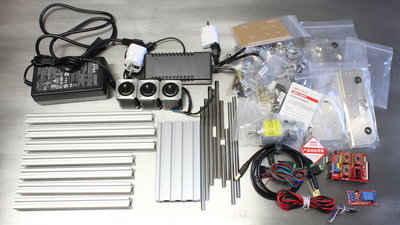
The T8 comes as a kit, but with no documentation. To make things easy for you, here comes my version... 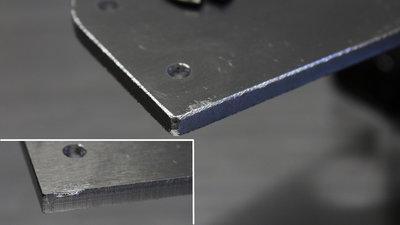
The parts come with scratches, but none of them affects the functionality. Grind all sharp edges of the parts with a file - you won't get bloody fingers during assembly or operation of the machine. 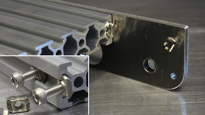
Special nuts with hexagon screws are used to mount parts on the aluminium profiles. Hexagon tools are part of the kit. 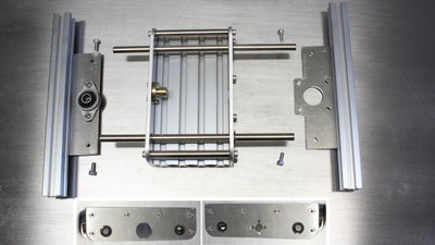
Use the round bars with the smaller diameter for the CNC table. 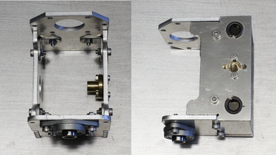
Don't assemble the X carriage mirror inverted. The brass lead nut must be on the right side when looking at the front, the ball bearing is on the bottom. 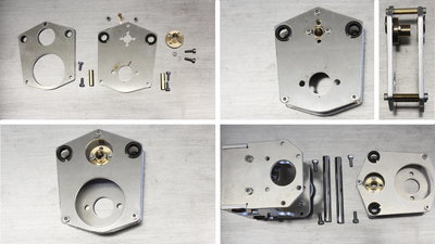
Z carriage. 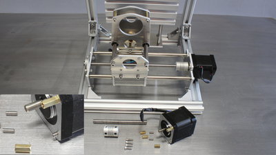
The stepper motor of the Z axis is mounted with spacer nuts. 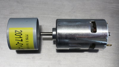
the iron ring on the spindle motor must be removed. 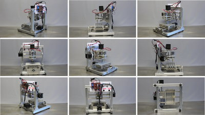
9 views on the assembled machine. Electronics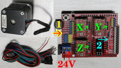
An Arduino Uno clone with a CNC shield (Version 3.00) on top is used to control the motors. As demonstrated in the video, cables with flat plugs must be soldered on the stepper motors. Plug the motors on the CNC shield besides the A4988 driver chips (X, Y, Z). The female plug of the 24V power supply is also connected to the CNC shield. Note the correct polarity! The pins maked by (1) on the photo run to the relay and provide 5V supply voltage. Note the correct polarity! the left (blue) pin has +5V, the right (yellow) pin is ground. The control pin of the relay must be pluged to the "Spindle Enable" (SpnEn) pin (2). 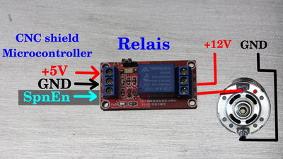
The spindle motor is turned on or off through a relay. Connect the left terminals with the accordant pins on the CNC shield (see figure above). The spindle motor is connected to the relay and the relay in turn is connected to the +12V pin of the female plug of the accordant power supply. Ground of the female plug is connected to ground of the spindle motor. 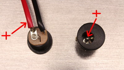
Note the correct polarity! The anode (plus, use red cable) must be connected to the central pin! Check the allocation of the soldering tag on back of the plug with a multimeter. 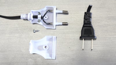
The adapters of the mains cables are a weak point of the kit. The plug of the 24V power supply can easily be replaced by a normal cable. I cut the cable of the 12V power supply to connect a new plug. Use a switchable multi plug to have an emergency stop function for your machine. 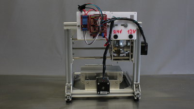
The electronic components are mounted on back of the machine. Software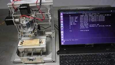
I wrote a tiny program, enabling keyboard control and sending G code files. The software runs in a Linux Terminal. The X axis must move to the right when pressing the right cursor key. If not, remove the plug of the X motor on the CNC shield and replug in 180 degree position. The CNC table must move to the front when pressing the cursor up key (spindle motor moves backwards in relation to the table). If not, replug the Y motor on the CNC shield in 180 degree position. The spindle motor must move up when pressing the page up key. If not, replug the Z motor in 180 degree position. You can get the (experimental) software I used in the video in the column Download. FirmwareMy T8 came with grbl v0.9 installed. The default values are:Grbl 0.9g ['$' for help] $0=10 (step pulse, usec) $1=25 (step idle delay, msec) $2=0 (step port invert mask:00000000) $3=6 (dir port invert mask:00000110) $4=0 (step enable invert, bool) $5=0 (limit pins invert, bool) $6=0 (probe pin invert, bool) $10=3 (status report mask:00000011) $11=0.020 (junction deviation, mm) $12=0.002 (arc tolerance, mm) $13=0 (report inches, bool) $14=1 (auto start, bool) $20=0 (soft limits, bool) $21=0 (hard limits, bool) $22=0 (homing cycle, bool) $23=0 (homing dir invert mask:00000000) $24=25.000 (homing feed, mm/min) $25=500.000 (homing seek, mm/min) $26=250 (homing debounce, msec) $27=1.000 (homing pull-off, mm) $100=800.000 (x, step/mm) $101=800.000 (y, step/mm) $102=800.000 (z, step/mm) $110=400.000 (x max rate, mm/min) $111=400.000 (y max rate, mm/min) $112=400.000 (z max rate, mm/min) $120=200.000 (x accel, mm/sec^2) $121=200.000 (y accel, mm/sec^2) $122=200.000 (z accel, mm/sec^2) $130=200.000 (x max travel, mm) $131=200.000 (y max travel, mm) $132=200.000 (z max travel, mm) Examples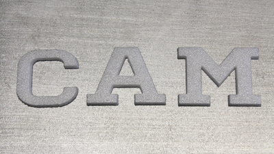
3mm Depron, characters height 28mm: 3mm Depron is cheap and easy to cut, thus it is a good material to start your experiments with this CNC. 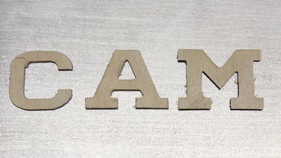
1mm plywood, characters height 28mm: Feedrate: 80mm per minute Depth per pass: 0.3mm 1mm plywood can be cut with ease. 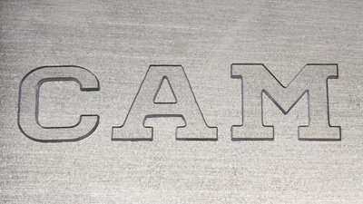
2mm Acrylic plastics, Characters height 28mm: Feedrate: 80mm per minute Depth per pass: 0.2mm Even the Acrylic plastics can ba cut with the machine. Caused by the V bit, the cutting edges are not perpendicular - the engraving machine with that tool is not meant to be used as router but it works in general. 
Engravinf wood (30x80mm): Feedrate: 80mm pro Minute Depth per pass: 0.3mm Total depth of the engraving 1.2mm The total depth of the engraving is 1.2mm. The engraving is clearly visible, but caused by the fiber structure of wood, the edges are a bit rough, thus to get a perfect result you must use some sandpaper to smoothen the surface. 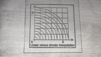
Engraving acrylic plastics: Line depth 1mm with 0.2mm per run, feedrate 80mm/min. The characters are 5mm high and clearly legible. 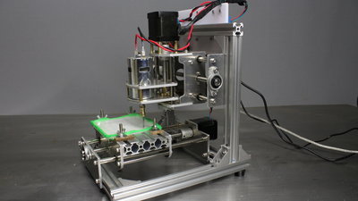
Plastics is a tricky material to process with a CNC machine. If the milling bit moves to slow along the path, the plastics starts melting by what the miller can no longer cut the material. In contrast with a too high feedrate, the V bit can't cut the plastics fast enough because of the low revolution speed of the milling motor - your milling bit will crack. With some water you can cool down the plastics and so avoid it from melting at the low feedrate of 80mm per minute used here. With pure water as coolant you can process the plastics even with this low power machine. Here I am using modeling clay to keep the cooling water on the acrylic plastics while engraving the material with the machine. With that you don't have to permanently keep an eye on the machine while processing the large G code file. 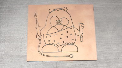
Engraving a copper plated board: Feedrate: 80mm per minute Dimensions of the graphics: 80x10mm Depth: 0.6mm, 2 runs If you can use this machine for creating curcuit boards? I will have a closer look, soon... <<< CNC v3.2.2 CNC 3018Pro Mostics >>> News The Project Technology RoboSpatium Contribute Subject index Archives Download Responses Games Links Gadgets Contact Imprint |
|
|