|
|
|
|
News The Project Technology RoboSpatium Contribute Subject index Download Responses Games Gadgets Contact <<< V-Plotter 2D printer from 3D printer >>> Turning a Zonestar 3D printer into a PlotterThe video about the Zonestar plotterGet the printer at Gearbest.com Have a look at the column Shopping Tips to get more special offers. The printer ships with no filament, thus don't forget to order filament. Simple version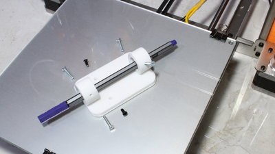
For the simple version of my plotter made of a 3D printer, only a holder for a pen is needed. Four additional 3mm screws as well as the two screws from the front fan are needed besides the printed part. With the 3mm screws at the rings you can adapt the holder to various pen diameters. The pen must be able to move in vertical direction to draw reliably even on not so flat surfaces. 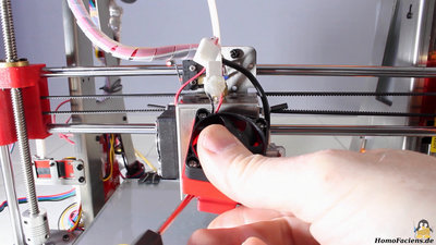
The pen holder replaces the fan on the front side of the print head. I am using a plug with protection against reverse polarity so that I can remove the fan quickly. 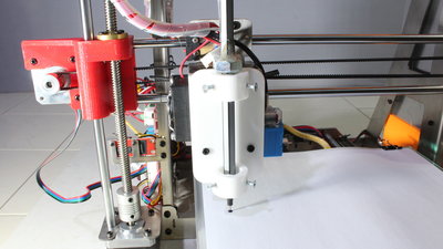
With hotglue I have fixed a 10mm nut on the pen for two reasons: The nut works as a stopper, preventing the pen from falling down and the additional weight keeps the pen on the surface while drawing lines. 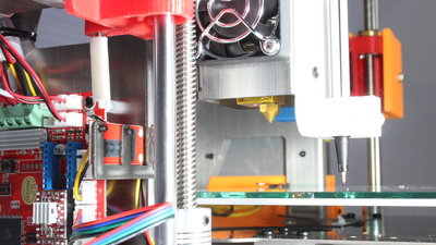
As you can see, the tip of the pen is clearly lower than the tip of the printer nozzle. That's why the end switch of the Z axis has to be triggered sooner than in printer mode. I have printed a couple of spacers to be able to adjust the new home position of the Z axis. Attach the spacer that fits best for your pen on the screw that triggers the end switch. Make sure that the tip of the pen hits the surface between two or three millimeters before the switch is triggered so that plotting even a rough surface works fine. Version with automatich pen changer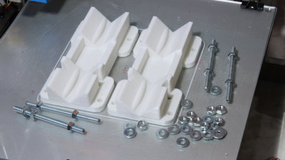
The second holder is designed to automatically pick up pencils. 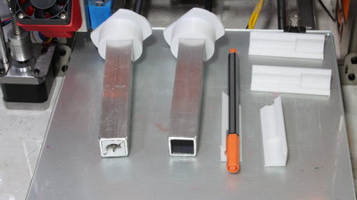
In my first version I was using aluminium square tubes with an edge length of 20mm - something I have always laying around in my workshop. 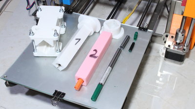
As seen later, printed square tubes work as well with only a minor loss of precision - as an advantage you can easily adapt them to the dimensions of nearly any pen. I had to trim the markers I am using to no more than 12cm to make them fit under the inactive pens that are parked at top of the plotter. 
The square tubes are guided by the new holder that can be adjusted through 4 screws to minimize backlash. Instead of the 10mm nut I am now using a printed part to prevent the square tubes from falling down. 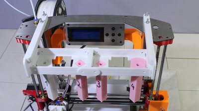
The subframe for the inactive pencils is mounted on top of the printer - to do so, I had to replace 4 screws by longer ones screwed in the other way round. Up to 4 markers can be parked in the subframe, enabling you to create colored plots. 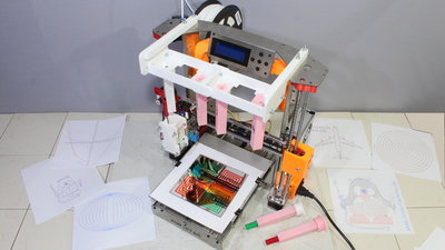
Assembled plotter. Software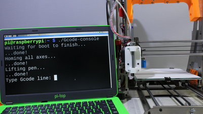
I have written two tiny programs for my plotter: The first one, written in "C" can transmit single lines with coordinates to the printer (plotter) trough USB. Furthermore you can send Gcode files to the plotter so that there is no need for using a SD card. 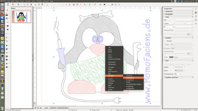
I am using a Perl script to generate Gcode files from "Scalable Vector Graphics", a file format that common vector graphics software can import or export - my choice is LibreOffice Draw. Before exporting, you must convert all paths into polygons. The only four colors accepted are black (rgb=0,0,0), red (rgb=255, 0, 0), green (rgb=0, 255, 0), and blue (rgb=0, 0, 255)! All other colors are replaced by one of these that matches best! DownloadYou can get my software written for the plotter as well as the 3D files for the printer conversion as download package. Note the "Readme.txt" in the package!Sample plots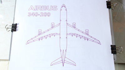
Airbus: 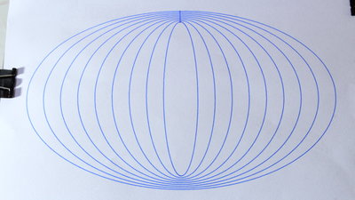
Ellipsis: 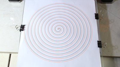
Spirals: 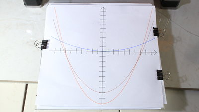
Parabolas: 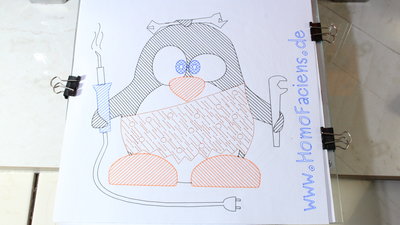
Colored HomoFaciens Logo: 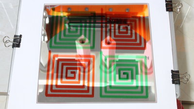
PErmanent markers on a mirror tile: <<< V-Plotter 2D printer from 3D printer >>> News The Project Technology RoboSpatium Contribute Subject index Archives Download Responses Games Links Gadgets Contact Imprint |
|
|