|
|
|
|
News The Project Technology RoboSpatium Contribute Subject index Download Responses Games Gadgets Contact <<< Rechargeable cells Band structure >>> Four stroke engineThe video about four stroke enginesYou can find the blender files, used to create the animated sequences at the column download. Saito FA-40The working principle of a four-stroke glow-plug engine will be demonstrated with the help of a little model motor used for RC planes. I recovered this piece of fine mechanics at my conglomeration case, filled with all the stuff accumulated during my model-making career. It is an almost unused FA-40 of the Saito company, featuring a cylinder capacity of 6.6ccm and a power output of about 500 Watt. Disassembled and well cleaned, I was able to reanimate the motor by using the fuel which was stored for ages in my garage. I just had to replace the mixture screw by a provisional one, because the original part wasn't in my case any longer.Carburetor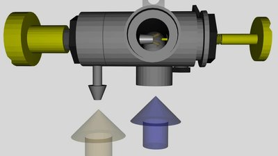
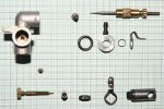
The carburetor creates an explosive mixture of fuel and the ambient air. The mixture screw operates like a valve, controlling the amount of liquid fuel flowing into the carburetor. By turning this screw out, more fuel is sucked out of the tank leading to a rich mixture. Turning the screw in lessens the fuel, hence a lean mixture is created. A perforated rotating barrel inside of the carburetor, which is connected to the throttle lever, is used to control the amount of air passing through this device. The drilled hole is pointing into the direction of the carburetor tube while the throttle is opened, hence the maximum amount of air is flowing into the carburetor. By turning the barrel with the help of the throttle lever, the transversal section is reduced and fewer air is passing the carburetor. A second needle valve is linked directly to the barrel which is used to control the fuel-air mix while the throttle is closed. This idle screw reduces the fuel when turned in, like the mixture screw, too. When the throttle is opened, the barrel and also the idle screw are moving slightly out of the carburetor, opening this valve slightly. This special movement is caused by a little screw in conjunction with a guidance at the barrel. Fuel and air enter the carbutetor and an explosive gaseous mixture of both components is coming out of the device. The scattered fuel evaporates at least for the most part. FuelThe fuel of the model motor consist basically of methanol (69%). Further components are Nitromethane (2%) and lubricants. In contrast to car engines, this motor has no separate oil reservoir, which is why these substance is mixed with the fuel.While operating, methanol is oxidized by aerial oxygen forming carbon dioxide and water: 2CH3OH + 3O2 → 2CO2 + 4H2O Oxygen and methanol react in a ratio ofCam shaft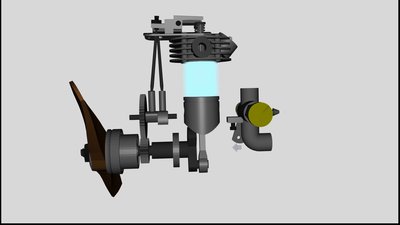
In a periodic process, the cylinder of the motor has to be filled with an explosive fuel-air mix and the burnt gas has to leave the engine. This process is controlled by at least two valves who are actuated by the cam shaft, consisting of a spindle with two bumps (=cam) and one gear wheel. The cam shaft is turned by the crankshaft with the help of a second gear wheel. Two small cylinders slide on the two cams and move up and down. The small cylinders move two pushrods which open the valves via the rocker arms in a cyclic way. The valves are closed by coil springs. The small cylinders are used to get a large bearing surface at the calms. The pushrods are twisting slightly during the cycles and if they would slide directly at the calms, deep scratches would be the result. Cylinder head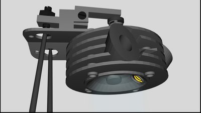
Two poppet valves and the glow plug are the main constructional elements located at the cylinder head. The two valves are actuated by the cam shaft via the push rods and the rocker arms. There has to be a small gap between the rocker arms and the top of the valve rod while the cam shaft is at the position "closed" to ensure that the valves are closed properly. The valves are not closed by the pushrods, but by small coil springs. The gap is called valve clearance and has to be adjusted while the engine is could. The given clearance for the Saito engine is 0.1mm. While the motor is running, the components are heated up in a different way and unequal thermal expansion of different materials leads to a modification of the clearance. The adjustment is done with the help of a small screw at one end of the rocker arm. If the correct clearance is adjusted, those screw is fixed by a nut. The glow plug is used to ignite the fuel-air mix supplied by the carburetor. During the starting procedure it is heated up by an electric current caused by a voltage of 1.2V. As soon as the motor is running, the glowing is induced by the combustion of the fuel. The hemispherical internal space of the cylinder head is called combustion chamber. CylinderLike assumed, this device is shaped like a hollow cylinder guiding the piston at his movement up and down. The cylinder liner, meaning the inner hollow cylinder of the device, is made of a special aluminum-silicon alloy and it must always be covered by an oil film, or else the heat caused by the friction would melt the materials of piston and cylinder immediately! This kind of "accident" is called piston seizure or galling.The inner diameter of the cylinder - which equals (almost) the diameter measurement of the piston - is called bore. CrankshaftThe crankshaft is actuated by the downward movement of the piston during the power stroke. Both devices are linked by the connecting rod or piston rod. There is an offset between the fastening point of the connecting rod (=crankpin) and the rotating axis of the crank. Thereby the highest respectively lowest point of the piston movement is determined. The distance between these two points is called stroke length or just stroke and equals the double radius of the attachment point.By multiplying the cross sectional area of the cylinder, usually given by bore * 2π with the stroke, you get the engine displacement, which is the volume swept by the piston in a single movement from top to bottom. The ratio between engine displacement + volume of the combustion chamber and the volume of the combustion chamber is called compression ratio: Where is: ε - compression ratio, VD - engine displacement, VC - volume combustion chamber Four stroke cycleWhen the engine is running, the piston is moving up and down while camshaft and crankshaft are rotating. A stroke refers to the full travel of the piston from its highest to its lowes point of movement. The farthest or nearest position between crankshaft and piston is called dead centre, because the movement of the piston "dies" at these points. The point of the farthest distance (=top position) is called top dead centre (TDC) while the point of the nearest distance (=lowest position) is called bottom dead centre (BDC). During a single stroke, the crankshaft rotates around its axis for 180degrees and the camshaft for 90degrees.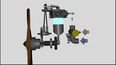
1. Intake stroke Let's start the observation at the top dead centre of the piston. The intake valve is opened and the piston starts moving downward. Thereby a negative pressure (in comparison to the ambient atmospheric pressure) is generated by what the fuel-air mix coming from the carburetor enters the motor. The intake valve is closed as soon as the piston reaches the bottom dead centre. This stroke is also called induction stroke 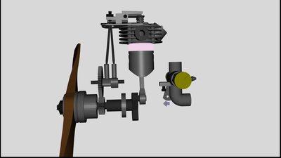
2. Compression stroke During the subsequent upward movement of the piston, the fuel-air mixture gets compressed, because by now both valves are closed. 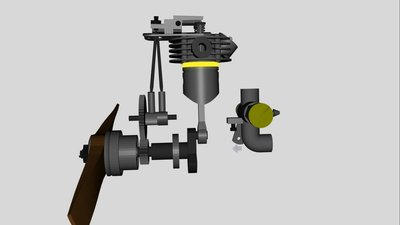
The composition of the fuel and the compression ratio of the motor have to be tuned in such a way, that the heating of the gas leads to an ignition of the gas mixture while the piston is close to the TDC. Those ignition is initialized by the glow plug. By burning the fuel-air mixture, the gas inside of the motor is heated up. 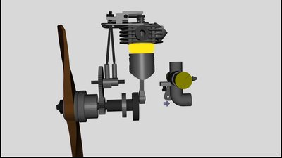
3. Power stroke The pressure of hot gas is significantly higher than those of cold gas and so the forces acting on the walls of the containment are higher, hence the piston is driven back down to the BDC by a higher force than required to compress the fuel-air mix during stroke 2. 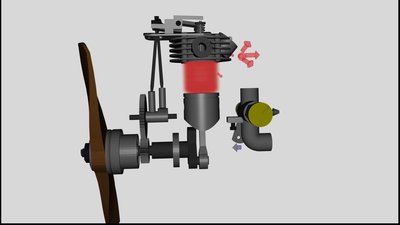
4. Exhaust stroke The exhaust valve opens and the burnt gas is evacuated from the motor while the piston is moving to the TDC once again. When reaching the TDC, the exhaust valve is closed. Energy is released to drive the crankshaft only during the power stroke. All other strokes extract kinetic energy from the rotating crankshaft and all devices connected to it (e. g. propeller). A high amount of this kinetic energy is needed to compress the fuel-air mix during stroke 2 especially near the TDC while the ignition process starts at the glow plug. To get a high running smoothness - meaning a homogeneous rotation speed of the crankshaft, a flywheel is usually attached to the crankshaft. The high mass of those flywheel leads to a low change in rotation speed while kinetic energy is supplied during the power stroke respectively extracted during the other strokes. Motor parts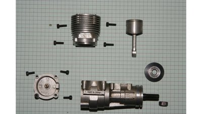
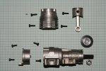
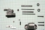
Piston (1) Connecting rod (2) Crankshaft (3) Housing of the crankshaft (4) Cylinder (5) 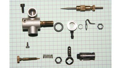
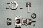
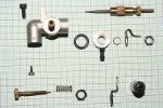
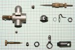
Carburetor (1) Mixture screw (2) (from another motor, doesn't fit to the FA-40) Gasket rings (3) Fuel connector (4) Idle screw (5) Throttle lever (6) Rotating barrel (7) 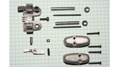
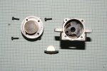
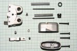
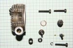
Mounting plate for the rocker arms (1) Cover tube for pushrods (2) Gasket (3) Pushrod (4) Axis of rocker arm (5) Rocker arm (6) Adjustment valve clearance (7) Cylinder head cover (8) 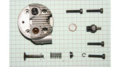
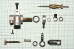
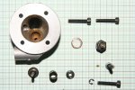
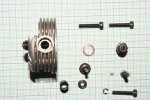
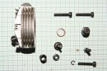
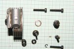
Cylinder head (1) Glow plug (2) Gasket (3) Valve (4) Coil spring (5) Locking device of coil spring (6) 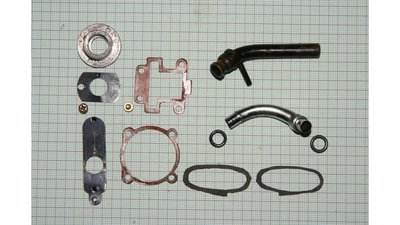
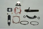
Exhaust (1) Inlet manifold (2) Gasket camshaft housing (3) Gasket crankshaft housing (4) Gasket Cylinder head cover (5) Choke (accessories kit) (6) Click at the preview photos to see the larger ones used to digitize the motor. 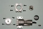


<<< Rechargeable cells Band structure >>> News The Project Technology RoboSpatium Contribute Subject index Archives Download Responses Games Links Gadgets Contact Imprint |
|
|