|
|
|
|
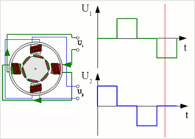
News The Project Technology RoboSpatium Contribute Subject index Download Responses Games Gadgets Contact <<< Stepper motor Synchronous motor >>> AC motorVoltage progression stepper motorIn the previous chapter the functionality of stepper motors was treated. The electromagnets of the stator are controlled by a voltage with alternating polarity. Let's have a closer look at the curve progression:
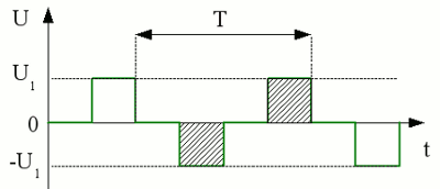
Voltage at electromagnet number 1: 
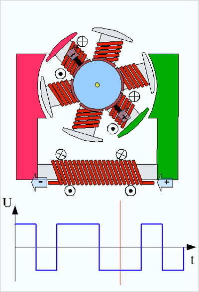
The voltage progression corresponds to a square wave jumping between +U1 and -U1. The duration of the pulses is constant, because the time span for a rotation around 30 degrees doesn't vary (assuming constant rotation speed). For these reasons the area between the x-axis and the voltage curve is added up to zero - the voltage progression belongs definitely to an AC voltage. The armature of the stepper motor rotates synchronously to the attached square voltage. At the example given above, the periodic time T equals exactly the rotational speed of the stepper motor. The polarity of the voltage is commutated as soon as the armature has been rotating until the north respectively south pole of two magnets points to the south respectively north pole of the enabled electromagnet. By increasing the periodic time (decreasing the frequency) the rotation pauses as soon as two magnets of the armature point to the poles of the enabled electromagnet. The rotation continues as soon as the second electromagnet is enabled. The animated drawing at the previous chapter shows a "choppy" rotation like that. With increasing frequency of the voltage (=reducing the periodical time) the armature can't follow the varrying magnetic field caused by the inducturs, thus it starts vibrating. The frequency of the attached voltage must meet the rotational speed of the stepper motor! Series wound motor with AC voltageWe already know the functionality of the series wound motor. At the chapter about DC motors it has been mentioned that the direction of rotation is independent from the polarity of the attached voltage. Let's have a look at such a machine with a square-wave voltage attached to it:
Series wound motor with attached square-wave voltage. If the polarity of the attached voltage alters at the connection terminals, the polarity of stator and rotor winding are altered because both coils are connected in series. For this reason the attractive respectively repulsive force between stator and armature persists. The direction of rotation is not altered. The frequency and the shape of the voltage progression (square-wave, sinusoidal) is not relevant in principle. Anyhow some chapters later we will observe the reasons why the rotation is influenced by the frequency of the attached voltage. To make the motor rotate in a different direction, the connection terminals of the stator winding have to be altered (in a mechanically or electronically way). <<< Stepper motor Synchronous motor >>> News The Project Technology RoboSpatium Contribute Subject index Archives Download Responses Games Links Gadgets Contact Imprint |
|
|