|
|
|
|
News The Project Technology RoboSpatium Contribute Subject index Download Responses Games Gadgets Contact <<< Optical sensors Measurement units >>> Computer mouseThe video about computer miceElectromechanical mouse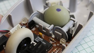
Electromechanical computer mice use a ball that's rolling on the surface. Two chopper wheels arranged perpendicularly are scanned by transmissive optical sensors detecting the motion of the ball. The working principle of this type of rotary encoders was treated in a previous chapter. Optical mouse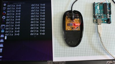
Modern computer mice usually don't need mechanical sensor wheels. The device shown here scans the surface using a tiny camera. The red light illuminates the surface. 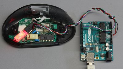
You can read the raw camera data of several chips: The module of this mouse has a resolution of 16 times 16, thus 256 pixel. Chips that can be used to read the raw camera data: PAN3101, ADNS-2051 (used here), ADNS-2083, ADNS-2610, ADNS-2620 and ADNS-5020. 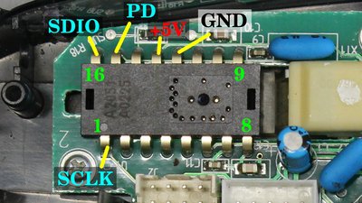
Pinout configuration of the A2052 Chip used in the video: +5V to +5V of Arduino Ground to ground of Arduino SCLK to digital pin 2 of Arduino SDIO an digital pin 3 of Arduino PD to digital pin 4 of Arduino The very experimental software is avaiable as download. 
The resulting image looks pixelated - you can barely read the characters underneath the mouse camera. The low resolution image is scanned with a high frequency so that even fast movements of the mouse can be detected. The underlaying text is magnified by the camera lense - in fact the character height is just 1mm. Data transmission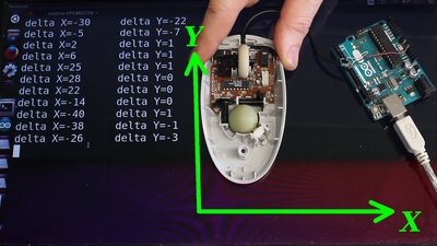
When using a computer mouse for motion sensing, the raw data of the camera is not needed. The internal sensor chip of the mouse processes the image data to get the accordant movement. Same as with the electromechanical mouse, only the offset in movement along the X and Y axis is transmitted through the PS/2 interface. Positive values represent a movement along the X axis to the right, negative values represent movement to the left. Same is for the Y axis. Positive values are transmitted when the mouse moves to the top, negative values indicate a movement to the bottom of the Y axis. 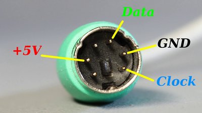
Note that the mouse must be PS/2 compatible. Those mice have a round, usually green colored plug with 6 pins. The four pins needed are ground, +5V, the clock signal and finally the pin for data transmission. +5V to +5V of Arduino Ground to GND of Arduino Clock signal (CLK) to digital pin 6 of Arduino Data to digital pin 5 of Arduino You can get the software used to read the sensor data in the column download <<< Optical sensors Measurement units >>> News The Project Technology RoboSpatium Contribute Subject index Archives Download Responses Games Links Gadgets Contact Imprint |
|
|