|
|
|
|
News The Project Technology RoboSpatium Contribute Subject index Download Responses Games Gadgets Contact <<< Encoder disc Optical sensors >>> Electromechanical rotary encoderThe video about the electromechanical encodersConstruction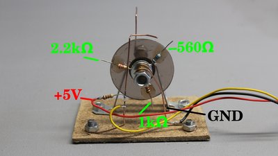
The rotor of this electromechanical rotary encoder is composed of three resistors having 560, 1000 and 2200 Ohms soldered on a washer. One wiper makes steady contact with the washer, pulling the potential to ground while the second contact is connected to the +5V pin of an Arduino through a 1 kiloohms resistor. Voltage divider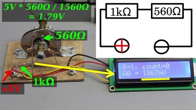
We get a reading of 5000mV, thus 5V whenever the switch is open. If the switch gets closed through the 560 Ohms resistor, a voltage divider composed of a 1 kiloohm and a 560 ohms resistor at 5V input voltage is formed. In theory we get a voltage drop of 1.79V across the 560 ohms resistor. 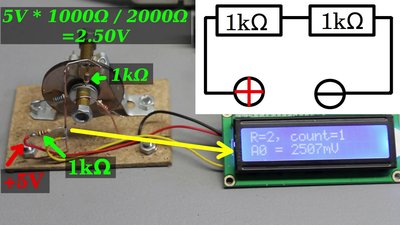
The recorded value is 2507mV as soon as the wire touches the 1 kiloohms resistor. The voltage divider is now composed of two 1 kiloohms resistors, by what we get a voltage drop of 2.5V in theory. 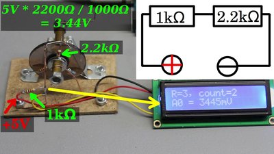
When making contact with the 2.2 kiloohms resistor, ge get 3445mV. In theory we get an output of 3.44V across a voltage divider composed of a 2.2 and 1 kiloohm resistor at 5V input voltage. The voltage reading is done by a microcontroller through an analog to digital converter. Whenever the rotary switch is closed, the reading at the analog input is either 1.79, 2.5 or 3.44V in theory. As demonstrated, the readings did never meet the theory, which is why the software accepts an error of plus minus 0.3V. Whenever the switch makes contact, the microcontroller can determine what resistor became part of the circuit. After breaking and making contact, the microcontroller can determine if a counterclockwise rotation or a clockwise rotation appeared or if the sensor was moving back and forth, making contact with the same resistor multiple times. Resistors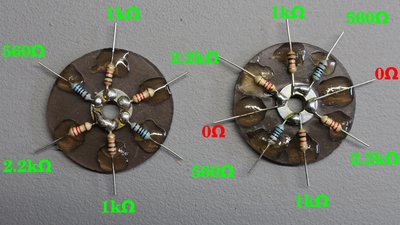
At least three different resistor values are needed. The larger the difference in potential between all "close" positions of the rotary switch, the better, thus more than three resistor values are not recommended. For an input voltage of 5V, the desired output voltages are 0V, 1.66V (5V / 3) and 3.33V (5V * 2 / 3) in theory. For the output voltage on a voltage divider there is: UOut = UIn * R2 / (R1 + R2) With given input and output voltage we get for R2:R2 = UOut * R1 / (UIn - UOut) Where is:UOut - Output voltage UIn - Input voltage R1 - Resistor at switch contact R2 - Resistor at rotor For an output voltage of 1.66V at 5V input voltage with a 1kΩ resistor at the switch contact, we get for R2 on the rotor disc: R2 = 1.66V * 1000Ω / (5V - 1.66V) = 459Ω For an output voltage of 3.33V we get: R2 = 3.33V * 1000Ω / (5V - 3.33V) = 1996Ω Contact bounce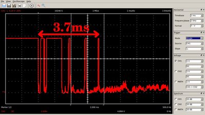
The switch contacts are made of springy metals, thus when they strike together they bounce apart several times before making steady contact. That event is recorded with an oscilloscope using a time base of 1ms: When the switch gets closed, there is a rapidly pulsed electric current for about 4ms instead of a clean transition from 5 to zero volts. 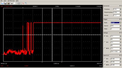
Those spikes also appear whenever the switch is opened: Now, the signal goes from zero to 5V multiple times until we get a steady HIGH signal. That common problem with nearly all electromechanical switches is called contact bounce. By software we can prevent the microcontroller from treating each pulse caused by the unwanted switch bounces as a sensor event: Only if a signal lasts for at least 50ms, which is more than 10 times the duration of contact bounce, a transition from LOW to HIGH or vice versa is treated as switch action. In doing so, we get a minimal duration of 100ms, thus 0.1 seconds for a single pulse. The maximum revolution speed for an encoder having 3 resistors is Circuit & software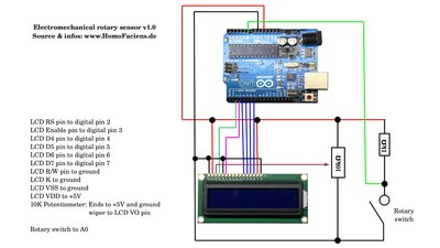
Software and schematics are available as download package <<< Encoder disc Optical sensors >>> News The Project Technology RoboSpatium Contribute Subject index Archives Download Responses Games Links Gadgets Contact Imprint |
|
|