|
|
|
|
News The Project Technology RoboSpatium Contribute Subject index Download Responses Games Gadgets Contact <<< R6 (WLToys) R8 (Zombie) >>> Jule UJ99-2815B (R7) - ConstructionThe Video about R7You can purchase the Jule UJ99-2815B on Gearbest. The base of R7, the Jule UJ99-2815B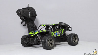
Rover number 7 is based on a commercially available RC model car named Jule UJ99-2815B. The dimensions are 22x15x10cm and the weight is 430g. Only the rear wheels that are connected through a hexagon rod are driven, so that the offroad capabilities are limited. The remote control in pistol grip design needs 2 AA batteries for operation that are not included in the package. The drive battery is composed of four Nickel Cadmium cells with a total voltage of 4.8V and a capacity of 700mAh, by what you get 10 to 15 minutes of driving fun. The battery is charged through a USB cable, the charging time is approximately 3 hours. Conversion to rover R7Parts list:
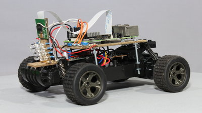
I used a Raspberry Pi model 3, a camera module and a DC converter. During first test runs I mounted it all on the car using pieces of fiber board. 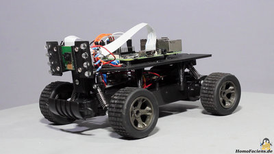
It looks better when having a 3D printer at hand. 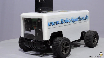
A cover protects the electronics from rain if you go for outdoor missions. It's 3D printed as well and the box shaped bodywork has lots of space for stickers. Electronics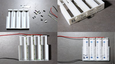
I have replaced the drive battery with 4 standard AA nickel metal hydride cells having a capacity of 1900mAh. The battery holder is 3D printed, because commercially available battery boxes are too large. The 4 battery cells fit into the box at the bottom of the car. Solder the wires on the terminals (stripes from a beverage can) before bending the metal or else you will melt the thin plastics quickly. Insert the batteries with all positive terminals pointing to the top (bottom right in the picture)! The terminals of the battery holder are coneccted accordingly (bottom left of the picture). 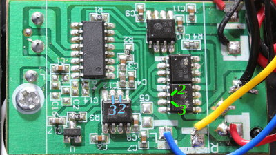
As demonstrated in the video, pins 2 and 3 are the inputs of the H bridges. The steering is controlled by the chip on bottom left, the drive motor by three of the chips being switched in parallel. Same as the Raspberry Pi, the microcontroller (large chip) on the board works with 3.3V logic level. 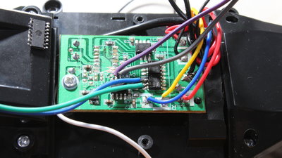
You must remove the microcontroller from the board or else the outputs of this chip will drive contrary to the GPIOs of the Raspberry Pi which will cause damage! Check if you did not bridge any traces while desoldering the chip. Also check if you did not bridge any pins while soldering the wires on the input pins of the H bridges. With a multimeter switched to continuity you can check if there is no conductive path between the pins of the H bridge! I am using 1 kiloohm resistors covered with shrinking tube to avoid damage of the Raspberry Pi in case something went wrong with the soldering work. Some hotglue keeps mechanical stress away from the soldering points. 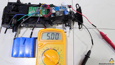
While the H bridges are connected directly to the battery, you must use a DC converter for the Raspberry Pi. I am using an adjustable converter, thus you must make sure the output voltage is indeed 5V before connecting the Raspberry Pi! 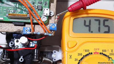
The voltage of the Nickel-Cadmium batteries that ship with the car should never drop below 3.6V. I am using a voltage divider composed of 3 resistors and two potentiometers to sense the battery voltage. Three points of the voltage divider are connected to GPIOs of the Raspberry Pi with pull-up or pull-down resistors being disabled by software. 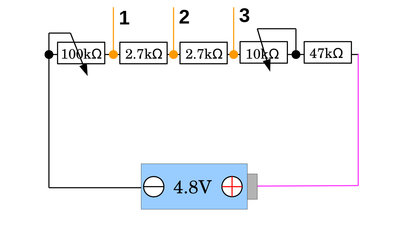
The output voltage of the battery is divided by the voltage divider. Point (3) detects the highest voltage of the three reading points. If the voltage at this point drops below a given value, R7 initiates the shutdown procedure to avoid deep discharge of the battery. The GPIOs of the Raspberry Pi can only be used as digital inputs, by what the state changes from HIGH to LOW if the voltage drops below 1.17V as demonstrated in the chapter about Physical Computing. Yopu must adjust the voltage diviter in such a way that you can read 1.17V at (3) whenever the lowest battery voltage is reached. For the Nickel-Cadmium battery that ships with the car we get 0.9V per cell, thus I have replaced the Nickel-Cadmium battery by standard AA Nicek-Metalhydride cells with a shutdown voltage of 1V per cell, Remove the cables from the Raspberry Pi during measurements do get exact readings! Instead of removing the wires, you can also disable the pull-up or pull-down resistors of the Pi by software (remember that the Raspberry Pi must be up and running). 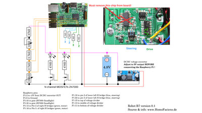
Circuit layout with the original board of the model car. 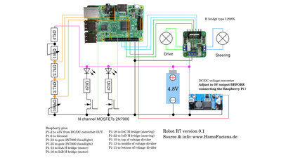
Circuit layout using a L298N double H bridge. Software/DownloadsThe software of R7 is still in an experimental state. The automatic sutdown at battery low state is not implemented, yet. The software is based on Raspbian lite - you can download that Linux distribution and get the installation instructions on the pages of the Raspberry Foundation. Use a fresh install of Raspbian lite!The installation procedure of my software that runs on top ot Raspbian Lite is written in the download package for R7, that also includes the 3D files and schematics. Test drivesThe barreries of R7 are good for an operation time of up to 2 hours which is why this rover isn't online all day long. Whenever an official mission of R7 is scheduled, you can see a countdown in the RoboSpatium as well as in the control center of R7.Follow me on Twitter (@RoboSpatium) if you'd like to get a notification whenever R7 starts a mission. <<< R6 (WLToys) R8 (Zombie) >>> News The Project Technology RoboSpatium Contribute Subject index Archives Download Responses Games Links Gadgets Contact Imprint |
|
|