|
|
|
|
News The Project Technology RoboSpatium Contribute Subject index Download Responses Games Gadgets Contact <<< R15 Hoverboard R19 Robot in a Suitcase >>> R18, Rover based on a ESP32-CAM board - ConstructionThe video about R18Have a click in the online shop of DFRobot, that's where I got the electronic parts of this Rover from. Remarks about the Rover design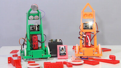
The basic idea of R18 is to put a really easy to replicate rover on the wheels. The robots I have built so far have always been designed for my RoboSpatium and the necessary adjustments are difficult for beginners to understand, especially on the software side. I have significantly reduced these hurdles with my R18 design because: 1.) the electronic components and 2.) the software are reduced to the bare essentials. Another benefit is that the price per rover is rather small, which is why I built 3 of them - all previous rovers are unique prototypes to this day. ... and finally I put a lot of time into this build instructions. If something is still unclear, leave a comment or get in contact with me otherwise. Assembly of the mechanics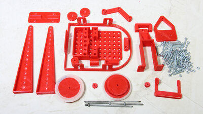
To make the mechanical components, I started two of my 3D printers. About 170g of filament were processed for the mechanics in two days per rover. The components of the red rover were created with my oldest 3D printer - not perfect, but sufficient for the mechanics. Everything is held together by 3mm screws with 20mm thread length, as well as a 30cm long piece of threaded rod and many nuts. If you don't like screws sticking out of the holes, you can also buy a pack of 3mm screws with 10mm thread length or use a hacksaw. 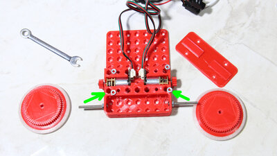
The assembly begins by screwing the axles for the wheels to the chassis. To do this, two 30mm long pieces of the threaded rod are cut to size, or a 30mm long screw is taken straight away. The pinions are fixed to the shaft of the motors with a drop of superglue. The shaft should stick out about 1mm. The motors are then pres fitted into the openings. To screw the cover, nuts must be inserted from the top of the chassis (see Figure 5) The two green arrows point to openings in the chassis where M3 nuts must be inserted for mounting the camera pole (see figure 7). 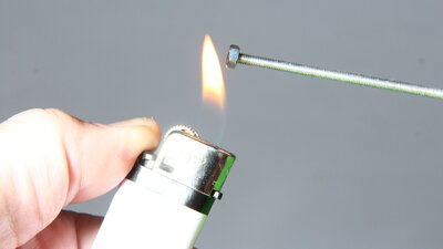
If the deep openings into which M3 nuts have to be inserted turn out to be a bit too tight after printing (which was the case with me), the nut can be carefully heated up with a lighter or a soldering iron. PLA, as I used for the parts, starts softening at 60°C. If you heat the nut too much or press it in too much, it can happen that it falls out on the other side. As with many thins in life, you have to develop the right feeling for a process. 
4 nuts must be inserted into the openings on top of the chassis to screw the motor cover on the underside. The wheels are held on the axle with two more nuts each. 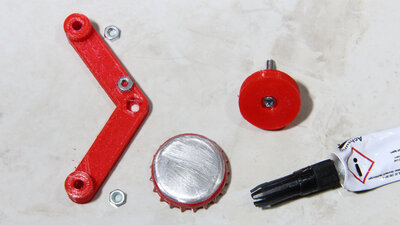
At the back there is a crown cap sliding on the surface to keep the Rover upright. A PLA washer is glued into this, through which a screw is inserted. The screw should not be glued in place, but must still be able to rotate freely in the hole after the plastic disc has been glued. Super glue or hot glue work pretty well. 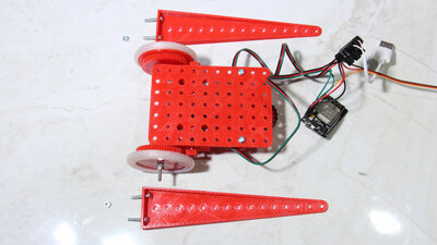
The camera pole is composed of two parts. 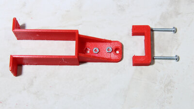
The holder for the camera servo and the battery. The base of the battery holder is not screwed flush with the chassis. A gap remains, otherwise the battery cannot be inserted. Only after inserting the power bank, the screws should be tightened until the battery is stuck. 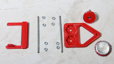
The holder of the ESP32 board and the upper sliding terminal are rotatably attached to the pole. To do this, two pieces of the threaded rod with a length of 65mm must be cut. The upper sliding contact is only required if the rover is not to be supplied with energy from a battery, but from an external source. 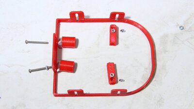
The bumper for the rover is optional, but it effectively prevents the robots from getting tangled in my RoboSpatium or driving to where they shouldn't ... 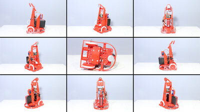
Different views on the finished robot. This should help to clear up the last remaining questions... Parts list:
Software upload via Arduino UNO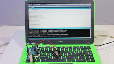
To get the software on the ESP32 boards, you need an Arduino UNO as a programmer and the Arduino IDE as software package. 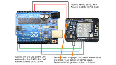
Wire up the Arduino Uno and the ESP32 as shown in the drawing: Arduino +5V to ESP32 +5V Arduino GND to ESP32 GND Arduino Pin 0 to ESP32 Pin UOR Arduino Pin 0 to ESP32 Pin UOT Arduino GND to ESP32 GND Before uploading the code, pin GND and IO0 on the ESP32 board must be bridged. Then press the reset button on the ESP32 board. After a successful upload, the bridge must be removed and reset must be pressed again. The ESP32 will then boot with the new firmware and should log into the WLAN. Preparing the Arduino IDEThe instruction is for Linux. I have tested the procedure with Linux Mint 20.4 and RaspberryOS.
"It doesn't work!"... is not a statement to which I can answer anything other than "Yes, and?"In each of the above steps, the individual programs give an output message on your screen. Read this information, because that's what the coders write them for! So if something goes wrong, you can see the reason in the messages. If you expect help from me, you have to give me: At which step an error was issued and Which message was to be read. It is also good to know which operating system (version?) You are working with - I can only really help you with Linux. You can get in contact with me by leaving a comment on this page or by sending me an email. You can find the address in the column contact. The statement "It works!" does not require any further information and I am delighted to hear or read it. Changes made to the webserver codeIf you not only want to upload my finished code, but also want to understand the basics of what I've changed, read through the following section. The changes listed here have already been implemented in the code of the download package and do not have to be made to operate the rover!The page "index.html" with the buttons is not written in plain text in the source code of the web server, but in compressed form. You can access the source text in a readable form by connecting to the rover using a browser and then calling up the page source text. The index.html with my changes made is included in plain text in the download package. The file "index-Camera-Server-WITHOUT-Rover-Control.html" is the original file of the camera server as it comes with the Arduino examples library. The description below is based on that unmodified file and the unmodified Arduino sketch in the Folder"Arduino-Camera-Server-WITHOUT-Rover-Control". Insert a checkbox for the onboard LED: In index.html search for the line: <div class="input-group" id="face_recognize-group"> and go a bit further down to the end of that section: </div> Below that line, insert the code block: <div class="input-group" id="flash-group"> <label for="flash">Flash</label> <div class="switch"> <input id="flash" type="checkbox" class="default-action"> <label class="slider" for="flash"></label> </div> </div> Insert control buttons "Drive forward" and "Drive Backward": In index.html search for the line: <section id="buttons"> Below that lne insert the lines: <button id="drive_forward">Drive Forward</button> <button id="drive_backward">Drive Backward</button> Search for the line: const stillButton = document.getElementById('get-still') Below that line insert: const DriveForwardButton = document.getElementById('drive_forward') const DriveBackwardButton = document.getElementById('drive_backward') Search for the line: enrollButton.onclick = () => { Above that line insert the lines: DriveForwardButton.onclick = () => { DriveForwardButton.innerHTML = 'Driving...' updateConfig(DriveForwardButton) } DriveBackwardButton.onclick = () => { DriveBackwardButton.innerHTML = 'Driving...' updateConfig(DriveBackwardButton) } Now the index.html must be transformed into compressed format. Copy and paste the index.html online at: https://gchq.github.io/CyberChef/#recipe=Gzip('Dynamic%20Huffman%20Coding','index.html.gz','',false)To_Hex('0x',16)Split('0x',',0x') Copy the source code to the "Input" area. Make sure all parameters are adjusted als follows: Compression: "Dynamic Hoffman Coding" Delimiter: 0x Bytes per line: 16 Split delimiter: 0x Join delimiter: ,0x After clicking on "Bake" the resulting source code is transformed into a coma separated list of HEX bytes in the "Output" section. Copy that text in the Arduino IDE in the "camera_index" tab. The Text to be replaced starts after the line: const uint8_t index_ov2640_html_gz[] = { and ends before the terminating "}". Remove the very first comma in the list! Now, you must correct the value for: #define index_ov2640_html_gz_len (4880) It specifies the number of bytes of the compressed index.html. This value is not displayed on the website and must therefore be calculated. The number of lines is indicated above the "output" field. Multiplied by 16 you get the number of bytes. Since the last line is not necessarily complete, the missing bytes must be subtracted! Now, changes in the tab "apt_http.cpp" have to be done: Search for the line: else if(!strcmp(variable, "face_recognize")) { Above that line, insert the block: else if(!strcmp(variable, "flash")) { #define LED_BUILTIN 33 pinMode(LED_BUILTIN, OUTPUT); digitalWrite(LED_BUILTIN, atoi(value)); } else if(!strcmp(variable, "drive_forward")) { #define LED_BUILTIN 4 pinMode(LED_BUILTIN, OUTPUT); digitalWrite(LED_BUILTIN, 1); } else if(!strcmp(variable, "drive_backward")) { #define LED_BUILTIN 4 pinMode(LED_BUILTIN, OUTPUT); digitalWrite(LED_BUILTIN, 0); } The code changed in this way must be uploaded onto the ESP32 as described above. Please note that the "Drive Forward" and "Drive Backward" buttons only switch the red LED on the back of the ESP32 board on and off! Electronics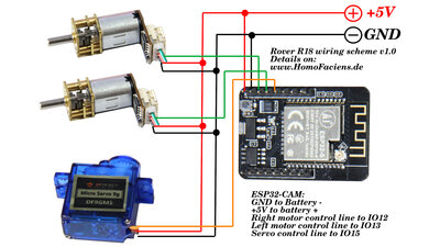
Besides the ESP32-CAM, only two mini geared motors, a micro servo and a powerbank are needed. 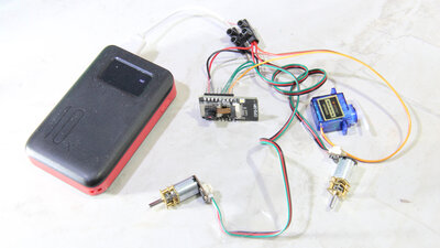
The wiring can be done without a soldering iron. In this case, the lines from ground and + 5V are joined in two screw terminals. The connection to the pins on the ESP32 board is made via the plug-in contacts of the servo and geared motors (control lines) or via so-called doupont or jumper cables (+ 5V and ground). 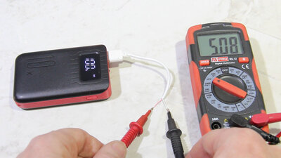
I cut through a micro USB cable, because the half with the type A plug is needed to connect the electronics to the power bank. The correct polarity is checked with a multimeter - there is obviously plus 5V on the light red line, as expected. DownloadThe 3D files of the printed parts, the circuit layout as well as the Arduino sketch are available as download package (2.8MB).Test drivesHave a look at my RoboSpatium to see what robots are currently available for a test drive. Have fun!<<< R15 Hoverboard R19 Robot in a Suitcase >>> News The Project Technology RoboSpatium Contribute Subject index Archives Download Responses Games Links Gadgets Contact Imprint |
|
|