|
|
|
|
News The Project Technology RoboSpatium Contribute Subject index Download Responses Games Gadgets Contact <<< R13 Mini-Stepper R15 Hoverboard >>> R14, pi-top[4] rover - ConstructionThe video about R14Mechanics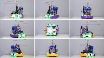
R14 is another tracked rover. The parts of the mechanics are made with a 3D printer. The central brain is a pi-top[4] Parts list:
Electronics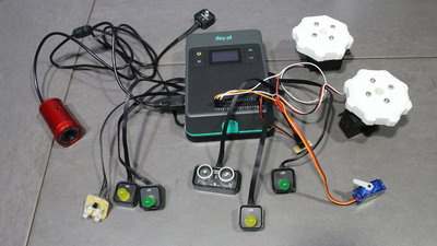
Central brain of R14 is a pi-top[4] (details about the computing "brick"). Thanks to the special socket, wiring of the vehicle is done faster than with any of my previous rover projects - the soldering iron is only used sporadically. Two standard servos for continuous rotation act as drive motors. These are connected to the 40-pin header on top of the case; the + 5V pin can deliver currents of up to 1.5A. The camera is tilted by a micro servo - this is also connected to the 40-pin header. The headlight is made of the LED modules from the "Foundation Kit", which are quickly connected with the cables included - R14 is my first rover with colorful lighting. Since the brightness of the LEDs is not particularly high, I soldered an additional module composed of 4 white LEDs. With that the electronics of R14 would be done, but the "Foundation Kit" also includes an ultrasonic and a light sensor, which I have also installed because wiring it up it is so simple. 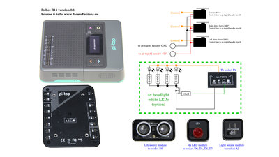
Circuit diagram of R14: The white LEDs are an option. External power supply (option)Using an external power supply is an option for skilled tinkerers! With the built-in battery, the rover runs for more than 2 hours, which is more than sufficient for normal operation.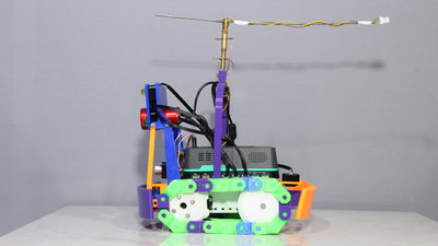
Power pole with anti twist mechanism for external power. There is a diode soldered between the +12V and ground wire in reverse polarity to protect the rover from reverse polarity. 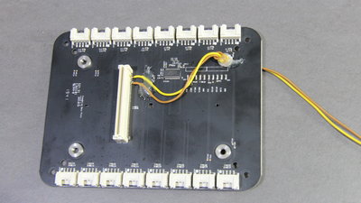
The two wires for external power are soldered to the socket. The yellow cable is +12V, the brown cable goes to ground. Details about the "pi-top maker achitecture (PMA)" interface are available on the pages of pi-top.com. SoftwareThe peripherals of R14 are controlled through a Python program that starts during boot process of pi-top OS. Through a website, the commands are forwarded to the Python program. For that reason, the web server Apache is installed on the pi-top[4]. Pictures from the USB camera are transferred by the program "Motion" that also runs on the pi-top[4]. To access the rover you must connect the pi-top[4] to your local WLAN. If all is set up, you simply have to point a browser to the ip address of your pi-top[4] to control the rover.DownloadCircuit diagram, installation procedure of the software as well as the 3D files are part of the download package (2.9MB).Test drive R14You can take control of R14 in my RoboSpatium. Have fun!<<< R13 Mini-Stepper R15 Hoverboard >>> News The Project Technology RoboSpatium Contribute Subject index Archives Download Responses Games Links Gadgets Contact Imprint |
|
|