Abbildung 1:
The LED circuit used in this chapter.
More about how to connect LEDs to GPIOs is written in the chapter on switching LEDs via GPIOs.
Which pins have which function can be found in the chapter on the hardware of the Raspberry Pi.
Abbildung 2:
The servo must be connected as shown in this figure. It is advisable to use a microservo, often also referred to as a 9g servo, as this does not draw a too high current.
Endless blinking
In the previous chapter we learned how to turn GPIOs on and off. With that, an LED connected to a GPIO either lights up with maximum brightness or not at all. In the previous example, however, we also made the LED flash once long and three times shortly before the program ended. In the following example we let the LED blink continuously, the Python script runs endlessly:
1
2
3
4
5
6
7
8
9
10
11
12
13
14
15
16
17
18
19
20
21
22
23
24
25
26
27
28
29
30
31
32
33
34
35
36
37
38
#!/usr/bin/env python
import RPi.GPIO as GPIO # needed to switch GPIOs
from time import sleep # needed to make command "sleep" available
# Choose BOARD pin numbering
GPIO.setmode(GPIO.BOARD)
# Set GPIO number 16 to output mode
GPIO.setup(16, GPIO.OUT)
# If a skript has to be stopped by 'ctrl+c', we must permanentely
# watch for such an event, which is done be the 'try:' statement.
try:
# Turn on LED with maximum brightness
GPIO.output(16, GPIO.HIGH) # Turn LED ON
sleep(2.0) # Do nothing for 2.0 seconds
GPIO.output(16, GPIO.LOW) # Turn LED OFF
sleep(1) # Do nothing for 1 second
# The statement (1 == 1) is true forever!
# With that, the while loop and so the skript never ends.
# You must press 'ctrl + c' to abort the script execution.
while (1 == 1):
GPIO.output(16, GPIO.HIGH) # Turn LED ON
sleep(0.1) # Do nothing for 0.1 seconds
GPIO.output(16, GPIO.LOW) # Turn LED OFF
sleep(0.9) # Do nothing for 0.9 seconds
except KeyboardInterrupt:
# This is the code section executed after 'ctrl+c' is pressed
# Script ends after that section.
print ("...keyboard interrupt detected\n")
GPIO.cleanup()
In the while loop, the LED is switched on for 0.1s and then remains switched off for 0.9s. The LED lights up for 0.1s in one second. The time required to execute the loop once is one second. The time needed for the switching processes of around 0.00001s = 10μs is ignored. The time it takes to run through the while loop once is referred to as the period (T), the switch-on time of the LED as the pulse width (t1). The pulse width in relation to the period is called the duty cycle and is usually given in percent. For the above example we get a duty cycle of:
100 * 0.1s / (0.1s + 0.9s) = 100 * 0.1s / 1s = 10%
If the script is running, you can see how the LED lights up for 2 seconds and then starts flashing shortly when the while loop is executed. The flashing is stopped by pressing the key combination 'ctrl + c'. Let's now shorten the period of the while loop by a factor of 2:
28
29
30
31
32
while (1 == 1):
GPIO.output(16, GPIO.HIGH) # Turn LED ON
sleep(0.05) # Do nothing for 0.05 seconds
GPIO.output(16, GPIO.LOW) # Turn LED OFF
sleep(0.45) # Do nothing for 0.45 seconds
The LED flashes at shorter intervals. The period is now reduced to just 0.05s + 0.45s = 0.5s, but the duty cycle has remained the same at 100 * 0.05 / 0.50 = 10%. Let's shorten the period by a factor of 100 compared to the first attempt:
28
29
30
31
32
while (1 == 1):
GPIO.output(16, GPIO.HIGH) # Turn LED ON
sleep(0.001) # Do nothing for 0.001 seconds
GPIO.output(16, GPIO.LOW) # Turn LED OFF
sleep(0.009) # Do nothing for 0.009 seconds
With a period of T = 0.001s + 0.009s = 0.01s and still 100 * 0.001s / 0.010s = 10% duty cycle, the individual switching processes of the LED can no longer be seen with the naked eye. When the script is executed, it can be seen that the LED lights up with maximum brightness for 2 seconds and then the brightness decreases significantly with the start of the while loop. The higher the duty cycle:
28
29
30
31
32
while (1 == 1):
GPIO.output(16, GPIO.HIGH) # Turn LED ON
sleep(0.003) # Do nothing for 0.003 seconds
GPIO.output(16, GPIO.LOW) # Turn LED OFF
sleep(0.007) # Do nothing for 0.007 seconds
the brighter the LED and the lower the duty cylcle:
28
29
30
31
32
while (1 == 1):
GPIO.output(16, GPIO.HIGH) # Turn LED ON
sleep(0.005) # Do nothing for 0.005 seconds
GPIO.output(16, GPIO.LOW) # Turn LED OFF
sleep(0.005) # Do nothing for 0.005 seconds
the darker it appears. In nested while loops we can vary the brightness of the LED:
1
2
3
4
5
6
7
8
9
10
11
12
13
14
15
16
17
18
19
20
21
22
23
24
25
26
27
28
29
30
31
32
33
34
35
36
37
38
39
40
41
42
43
44
45
46
47
48
49
50
51
52
#!/usr/bin/env python
import RPi.GPIO as GPIO # needed to switch GPIOs
from time import sleep # needed to make command "sleep" available
# Choose BOARD pin numbering
GPIO.setmode(GPIO.BOARD)
# Set GPIO number 16 to output mode
GPIO.setup(16, GPIO.OUT)
try: # Watch for interrupt events
# Turn on LED with maximum brightness
GPIO.output(16, GPIO.HIGH) # Turn LED ON
sleep(2.0) # Do nothing for 2.0 seconds
GPIO.output(16, GPIO.LOW) # Turn LED OFF
sleep(1) # Do nothing for 1 second
while (1 == 1): # This while loop runs forever
loopCount = 0
while (loopCount < 150): # Loop runs 150*(0.001s+0.009s)=1.5s
GPIO.output(16, GPIO.HIGH) # Turn LED ON
sleep(0.001) # Do nothing for 0.001 seconds
GPIO.output(16, GPIO.LOW) # Turn LED OFF
sleep(0.009) # Do nothing for 0.009 seconds
loopCount = loopCount + 1
loopCount = 0
while (loopCount < 150): # Loop runs 150*(0.003s+0.007s)=1.5s
GPIO.output(16, GPIO.HIGH) # Turn LED ON
sleep(0.003) # Do nothing for 0.003 seconds
GPIO.output(16, GPIO.LOW) # Turn LED OFF
sleep(0.007) # Do nothing for 0.007 seconds
loopCount = loopCount + 1
loopCount = 0
while (loopCount < 150): # Loop runs 150*(0.005s+0.005s)=1.5s
GPIO.output(16, GPIO.HIGH) # Turn LED ON
sleep(0.005) # Do nothing for 0.005 seconds
GPIO.output(16, GPIO.LOW) # Turn LED OFF
sleep(0.005) # Do nothing for 0.005 seconds
loopCount = loopCount + 1
except KeyboardInterrupt:
# This is the code section executed after 'ctrl+c' is pressed
# Script ends after that section.
print ("...keyboard interrupt detected\n")
GPIO.cleanup()
If you start the script, the brightness of the LED changes every 1.5s.
Pulse width modulation is a common method for dimming LEDs or generally for power control of a load connected to a GPIO. That's why there is a function in Python that does exactly what we do in the nested while loops. However, it is not the period of the pulse width signal that is handed as a parameter, but the frequency (f) which is the reciprocal of the period:
f = 1 / T
For the previous example we get f = 1 / (0.003s + 0.007s) = 1 / 0.01s = 100Hz.
The Python function used in the following examples is based on the "pigpio" software package, which is preinstalled on the current versions of RaspianOS. If this is not the case, the package can be installed with:
sudo apt-get update
sudo apt-get install pigpio
To make the functions work, the so-called pigpio daemon must be started before the script is executed:
sudo pigpiod
You can start the daemon automatically during boot process:
sudo systemctl enable pigpiod
Using those Python functions, the script needs significantly fewer command lines:
1
2
3
4
5
6
7
8
9
10
11
12
13
14
15
16
17
18
19
20
21
22
23
24
25
26
27
28
29
30
31
32
33
#!/usr/bin/env python
from time import sleep # needed to make command "sleep" available
from gpiozero import Device, PWMLED # needed to switch LED with pwm signals
# The older Raspberry Pi 1 or Pi Zero require to set the pin factory
from gpiozero.pins.pigpio import PiGPIOFactory
try: # Watch for interrupt events
# Pin factory for older Raspberry Pi models
Device.pin_factory = PiGPIOFactory()
# Set GPIO 16 to pwm mode with a base frequency of 100Hz
# Duty cycle is between 0.0 (=OFF) and 1.0 (=fully ON)
# For example 0.105 equals 10.5% duty cycle
# Initial duty cycle is 0.0
pwm16 = PWMLED("BOARD16", True, 0, 100)
while (1 == 1): # This while loop runs forever
pwm16.value = 0.1 # Set LED to 10% duty cycle
sleep(1) # Do nothing for 1 second
pwm16.value = 0.205 # Set LED to 20.5% duty cycle
sleep(1) # Do nothing for 1 second
pwm16.value = 0.4 # Set LED to 40% duty cycle
sleep(1) # Do nothing for 1 second
pwm16.value = 1.0 # Set LED to 100% duty cycle
sleep(1) # Do nothing for 1 second
except KeyboardInterrupt:
# This is the code section executed after 'ctrl+c' is pressed
# Script ends after that section.
print ("...keyboard interrupt detected\n")
I leave it up to you to explore the following script that creates a mini lightshow using two LEDs:
1
2
3
4
5
6
7
8
9
10
11
12
13
14
15
16
17
18
19
20
21
22
23
24
25
26
27
28
29
30
31
32
33
34
35
36
37
38
#!/usr/bin/env python
from time import sleep # needed to make command "sleep" available
from gpiozero import Device, PWMLED # needed to switch LED with pwm signals
# The older Raspberry Pi 1 or Pi Zero require to set the pin factory
from gpiozero.pins.pigpio import PiGPIOFactory
try: # Watch for interrupt events
# Pin factory for older Raspberry Pi models
Device.pin_factory = PiGPIOFactory()
pwm16 = PWMLED("BOARD16", True, 0, 100)
pwm22 = PWMLED("BOARD22", True, 0, 100)
# Define varying duty cycles for the LEDs
dutyCycle16 = 0.0
dutyCycle22 = 0.0
while (1 == 1): # This while loop runs forever
# Raise dutycycles
dutyCycle16 = dutyCycle16 + 0.01
dutyCycle22 = dutyCycle22 + 0.02
# Make sure that dutycycles are never greater than 1.0 (=100%)
if (dutyCycle16 > 1.0):
dutyCycle16 = 0.0 # start over with 0% duty cycle
if (dutyCycle22 > 1.0):
dutyCycle22 = 0.0
pwm16.value = dutyCycle16
pwm22.value = dutyCycle22
sleep(0.05) # Do nothing for 0.01 seconds
except KeyboardInterrupt:
# This is the code section executed after 'ctrl+c' is pressed
# Script ends after that section.
print ("...keyboard interrupt detected\n")
Servo
Abbildung 3:
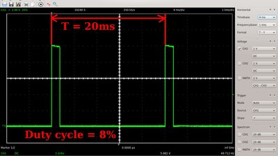
Servos are also controlled by pulse width modulation:
The frequency of the control signal must be 50Hz while the duty cycle varies between 5% (=-45°) and 10% (=+45°). The middle position corresponds to a duty cycle of 7.5%
There is more about this in the chapter on servos.
Since servos are very common drives, there are special functions available in Python, which make use of a 50Hz frequency. The position of the servo lever is not specified in degrees or the pulse width, but handed as a value ranging from -1.0 (=-90°) to +1.0 (=+90°), where 0.0 corresponds to the center position of the servo lever:
1
2
3
4
5
6
7
8
9
10
11
12
13
14
15
16
17
18
19
20
21
22
23
24
25
26
27
28
29
30
31
32
33
34
35
36
#!/usr/bin/env python
from time import sleep # needed to make command "sleep" available
from gpiozero import Device, Servo # Needed for Servo control signals
# The older Raspberry Pi 1 or Pi Zero require to set the pin factory
from gpiozero.pins.pigpio import PiGPIOFactory
try: # Watch for interrupt events
# Pin factory for older Raspberry Pi models
Device.pin_factory = PiGPIOFactory()
# Control line of Servo connected to pin 1_12 on Raspberry Pi
servo12 = Servo("BOARD12")
# Create variable for servo angle
servoAngle = -1.0
while (1 == 1): # This while loop runs forever
# Set servo angle
servo12.value = servoAngle
# Raise servo angle
servoAngle = servoAngle + 0.1
# Make sure that servoAngle doesn't get greater than 1
if (servoAngle > 1.0):
servoAngle = -1 # start over with -1
sleep(1.0) # Give the servo arm some time to settle
except KeyboardInterrupt:
# This is the code section executed after 'ctrl+c' is pressed