|
|
|
|
News The Project Technology RoboSpatium Contribute Subject index Download Responses Games Gadgets Contact <<< Switching P-channel MOSFETs Amplifying ICs >>> Demo board of a freely programmable, double H-BridgeVideo showing details of the demo board.
The PCB shown in the video was provided to me by PCBWay. You can commission your own circuit board on their website: About the boardAnother chapter (including video) on the assembly of the PCB is available on my second project "How Open Is This Gadget?"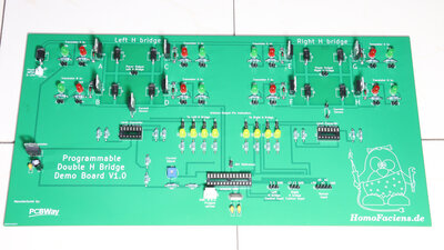
In my series on "Physical Computing" chapters on motor controls should not be missing. These start with switching transistors and then of course quickly lead to H-bridges. Since the switching states of more than just one transistor have to be taken into account in these circuits in order to understand how they work, I designed a demo board that uses LEDs to make the invisible visible. 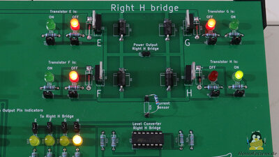
There are two H-bridges on the board, each consisting of four MOSFETs. There is a red and a green LED next to each of these transistors. If the relevant transistor is switched on, the green LED lights up, if the transistor is switched off, the red one lights up. 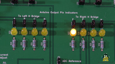
8 control pins of the microcontroller are required for a total of 8 transistors. The yellow LEDs show the switching states of the GPIOs used as outputs. If the relevant pin is at HIGH level, the connected LED lights up. All LEDs can be disconnected from the circuit using jumpers. Changes on the layout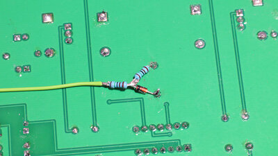
Controlling a stepper motor works as intended, but since I didn't just want to show "what can be done", but also explain "how it works", the circuit board layout wasn't perfect. So let's take a look at the changes I implemented after my first tests: Accross the resistor, that is implemented as a current sensor, a voltage drop of significantly less than 5V occurs in normal operation, something the ATMega328 microcontroller can handle without any problems. However, I would also like to use the board to demonstrate cases that are outside of the normal operating conditions and there can drop below the full supply voltage of 12V and more. Since the microcontroller would be destroyed if this voltage were applied, I soldered a 4.3V zener diode and two other resistors to each of the two current sensors on the back of the board. However, I would also like to use the board to demonstrate cases that are outside of the normal operating states at which up to the full supply voltage, which is usually more than 7V, might drop accross the resitor. Since the microcontroller would be destroyed if this voltage was applied to a GPIO, I soldered a 4.3V zener diode and two more resistors to each of the two current sensors on the back of the board. 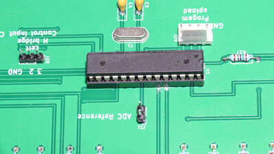
I had to cut the tracks running from the current sensor directly to the microcontroller on top of the board. 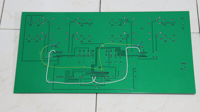
Two cables on the bottom side now lead from the Z diodes to the two analog inputs (green). Another change adresses the control pins of the transistors: Since not all microcontroller pins have hardware pulse width support, I swapped two of these output pins, which makes programming much easier. Again, I had to cut through the tracks on the circuit board and reconnect the pins on the bottom side with two more wires (white). 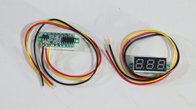
Then I found cheap mini voltmeters on the internet and quickly came up with the idea of installing them on the circuit board as well. 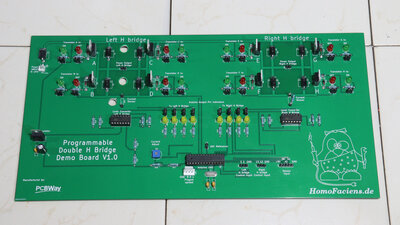
To hide their wire routing, I drilled 3 holes in the board. 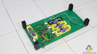
Each of the mini voltmeters is fed with electrical energy by a battery, independently of the H bridge's supply voltage. One battery for all voltmeters will not work, because in doing so, short circuits would be caused on the board. The bottom side of the PCB no longer looks as tidy and professional as the top - this is where the tinkerer in me comes back to daylight! It should be programmable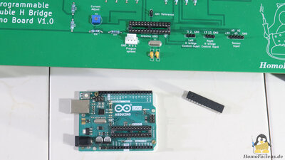
"Physical computing" means that the hardware is programmable. This demo board uses an ATmega328P microcontroller. I took this from my Arduino UNO and put it on the socket of the PCB. So that the microcontroller can still be programmed via the UNO board without having to swap the chip between the UNO board and the PCB, I joined pins 0, 1, reset and ground with a four pin connector. 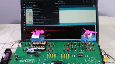
If these pins are connected to the UNO board, the microcontroller can be programmed and data can be exchanged via the USB interface. Design files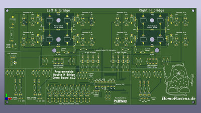
The current hardware version is V1.3 You can get the design files created with KiCAD as Download package (4.5MB). Components:4x Q1, Q3, Q5, Q7 P-Channel MOSFETs: IRF9540N4x Q2, Q4, Q6, Q8 N-Channel MOSFETs: IRF540N 2x IC1, IC2 4-Fach Op-amp: L324N 1x LM7805 5V linear regulator 1x C1: 0.1μF 1x C2: 33μF Elektrolytical 2x C3, C4: 15pF 7x C5 - C11: 0.1μF 65x R1 - R65: 1.5kΩ 7x R66 - R72: 510Ω 7x R73 - R79: 100Ω 1x Potentiometer: 100kΩ 9x Schottky Diode D1-D8, D41: SB5100 8x Zener diode D9 - D16: 12V 9x Zener diode: D42 - D50: 4.3V 8x LED 5mm D25 - 32: Red 15x LED 5mm D17 - D24, D51 - D57: Green 8x LED 5mm D33 - D40: Yellow 56x Jumper + 2 pin male pinheaders, 2.54mm 2x 3 Pin header, male 2.54mm 4x 4 Pin header, male 2.54mm 1x 5 Pin header, male 2.54mm 2x 14-Pin Socket 1x 28-Pin Socket 1x 16MHz Crystal 7x Push buttons SW1 - 7 1x Arduino UNO (with removeable ATmega328) Sourcing partsWhen buying components via the affiliate partner links I have listed in the table (or through the banners on my pages) you help to keep my my projects going - many thanks!Clicking on the links does not mean you have to buy - you can simply browse through the pages ;-) Of course, supporting my freely accessible educational platform without shopping but by making a donation or becoming a Patreon also works. Many thanks to everyone who already sent me an obol! If you know more MOSFETs that are good for amplifying signals of 5V or 3.3V GPIOs or common, cheap power diodes, please leave a comment on this page.
<<< Switching P-channel MOSFETs Amplifying ICs >>> News The Project Technology RoboSpatium Contribute Subject index Archives Download Responses Games Links Gadgets Contact Imprint |
|
|