|
|
|
|
News The Project Technology RoboSpatium Contribute Subject index Download Responses Games Gadgets Contact <<< Imprint ...to be continued. >>> Direct granules extruder V7.1The video about Direct Granules Extruder V7.1.Design von Extruder V7.1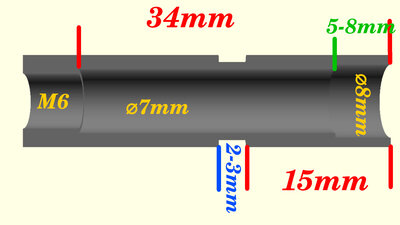
As before, the extruder tube is based on a 40 mm long, stainless steel M6 threaded sleeve. The objective for the development of Version 7.1 was to further simplify the design. The previous version, V7.0, utilized a brass insert to line the excessively rough inner walls of the extruder tube. In Version 7.1, the internal threading is removed using a 6.8 mm drill bit, and the resulting bore is subsequently enlarged to a diameter of 7 mm using a hand reamer. The use of the hand reamer ensures that the inner surface of the bore is smoother; consequently, the extruder functions effectively even without the insert. At the upper end, the bore is enlarged to a diameter of 8 mm to a depth of 6-8 mm. While the extruder will, in principle, function even without this stepped bore, this modification at the upper end increases the material throughput per screw revolution by up to 20%. At the upper edge, the threaded sleeve is chamfered, using a 90° countersink, to a diameter extending nearly to the sleeve's outer diameter. Three notches cut into the upper edge further enhance the material feed. 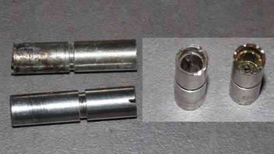
Extruder tube V7.1 (bottom and left) in comparison with V7.0. 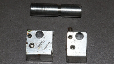
To improve heating of the larger hot zone volume in Extruder V7.1, I increased the length of the aluminum block containing the heating element to 20mm. However, the resulting improvement is not particularly significant; consequently, the 15mm long heating block from Version 7.0 remains fully functional. The download package includes 3D files containing drilling templates for both versions. All other components remain unchanged compared to the predecessor, Version 7.0. DownloadThe 3D files and the extruder sketch are available as a download package.Test prints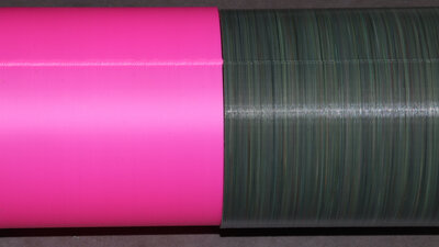
Holow cylinder Dimensions: 100x100x100mm Wandstärke: 0.7mm Layer height: 0.4mm Extrusion width: 0.7mm Print speed: 30mm/s The hollow cylinder was not printed in vase mode, as this mode is rarely relevant in practical applications. At the transition to the next layer, the printing motion briefly pauses in the X/Y direction. The resulting seam demonstrates how effectively the extruder can switch from maximum volumetric throughput to zero and back to the maximum value. I had performed the same test on the Prusa using the original filament extruder (shown on the left in the image), and in that case, the seam is significantly more prominent. 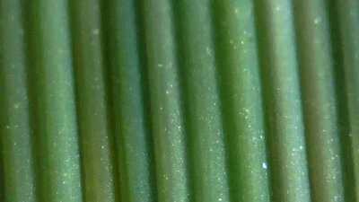
Hohlow cylinder Dimensions: 100x100x100mm Wandstärke: 0.7mm Layer height: 0.4mm Extrusion width: 0.7mm Print speed: 30mm/s A view through the microscope reveals that no air bubbles appear on the wall. 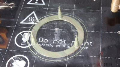
Test print Stringing Dimensions: 3 Cones with 10x1x30mm Wall thickness: 0.7mm Layer height: 0.2mm Extrusion width: 0.5mm Print speed: 30mm/s Overall, only very few, very thin strands are spun between the cones, which can be easily removed by hand after printing. 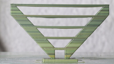
Test print Bridging Dimensions: Bridges from 8 - 65mm Layer height: 0.2mm Extrusion width: 0.5mm Print speed: 30mm/s During bridging, the back pressure at the nozzle tip drops abruptly at the edge where the print transitions into the gap. The extruder evidently handles this without any difficulty. Furthermore, the extrusion remains sufficiently consistent to ensure that none of the strands snap. In principle, bridging poses no problem. The extent to which the strands printed in mid-air sag depends not only on the extruder but also - among other factors - on the cooling provided by the fans. I did not engage in excessive fine-tuning here; for the moment, the focus is solely on the extruder itself, rather than on the combined system of extruder and printer. 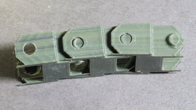
Track link Dimensions: 27x25x12mm Layer height: 0.2mm Extrusion width: 0.5mm Print speed: 30 und 80mm/s The three chain links were printed at different speeds and acceleration values. Right: 30 mm/s at an acceleration of 500 mm/s2 Center: 80 mm/s at an acceleration of 500 mm/s2 Left: 80 mm/s at an acceleration of 10,000 mm/s2 At full acceleration, a distinct ripple pattern is visible on the surface. The 1,037 g of mass moving along the X-axis cause the entire printer mechanism to vibrate visibly. 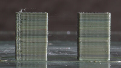
Test Retract Dimensions: Two Blocks 10x5x10mm with 10mm distance Layer height: 0.2mm Extrusion width: 0.5mm Print speed: 30mm/s Particular attention should be paid to the left rectangular block, where printing on the front face resumes - following a retraction - moving from left to right. Small gaps form at this location. The underlying cause is a small "blob" of material that forms at the start of the print path due to an excess of extruded plastic. During a retraction, the extruder screw is rapidly rotated backward by a specific angle - let's say by one full revolution. During the subsequent "deretraction", a rapid forward rotation occurs through the exact same angle - that is, again, one full revolution. Theoretically, the volume of material lifted up inside the tube during retraction should equal the volume subsequently pushed back down during deretraction; yet, material oozes out of the nozzle tip - but why? Well, during a retraction, a small amount of air is drawn into the nozzle; some of this air then rises up through the extruder as the molten plastic flows downward under the influence of gravity. Consequently, during deretraction, the plastic that gets extruded is the material that had flowed toward the nozzle - driven by gravity - during the retraction phase and the print head's travel to its next destination point. The "blob" that forms at the point of deretraction is located along the inner surface of the two outer perimeter walls. As the printer subsequently prints the outermost perimeter and moves over this "blob," it induces vibrations; this results in the formation of a protruding edge followed by a visible gap. 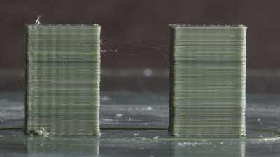
Test Retract Dimensions: Zwei Quader zu 10x5x10mm im Abstand von 10mm Layer height: 0.2mm Extrusion width: 0.5mm Print speed: 30mm/s The parameter that needs to be adjusted in Prusa Slicer is "Extra length at deretract"; this value must be set to a negative figure - in my specific case, -1 mm. What this approach fails to account for is that, immediately afterward - for a distance of a few millimeters - slightly too little material is actually extruded, as the previously drawn-in air completely exits the extruder again; addressing this would require implementing new parameters in the software. Thanks to the negative value applied during the deretraction phase, at least no "blobs" are printed anymore, and the edges turn out clean, without any gaps. 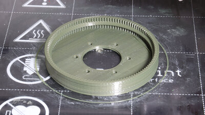
Gear Dimensions: 85x85x12mm Layer height: 0.2mm Extrusion width: 0.5mm Print speed: 60mm/s <<< Imprint ...to be continued. >>> News The Project Technology RoboSpatium Contribute Subject index Archives Download Responses Games Links Gadgets Contact Imprint |
|
|