|
|
|
|
News The Project Technology RoboSpatium Contribute Subject index Download Responses Games Gadgets Contact <<< Current, resistance and power Magnetism >>> Constant-resistance networkLinear circuitAt the previous chapter we recognized resistance as an inevitable side effect of moving charges inside a metal wire. A piece of wire with the length l has a resistance of the value x. If the length of the wire gets doubled, the resistance of the wire gets doubled, too. The wire with the double length consists in principle out of two half's - each with the length and the resistance of the original wire - in a linear circuit. By doubling the length of the wire, we realized our first circuit - a linear circuit. For constant resistance at constant voltage inside linear circuits there is:In a line circuit consisting out of n resistors, the current through each single resistor is the same ( IG ). Therewith the voltage across the resistors can be calculated by: According to this, we get for the electrical power: Where is: PG - Total Power, UG - total voltage, IG - total current, R1, R2, R3, Rn - resistance So we can see that the voltage across a resistor in a line circuit is proportional to the value of it's resistance. Across the resistor with the greatest resistance, there is the greatest voltage and therefore the greatest amount of power transformed into heat. Parallel circuitLet's put the two pieces of wire side by side. Now both are connected to the same voltage and both still have the same resistance. Therefore the electric current through both wires is the same, meaning the total current has been doubled. The original resistance was R = U / I and in parallel we get R = U / (2 * I). The total resistance is just half as much as those of a single wire. Fore resistors in a parallel circuit with constant voltage there is:The same voltage at each resistor gives a total current for the circuit: For the power we get: Where is: PG - Total Power, UG - total voltage, IG - total current, R1, R2, R3, Rn - resistance The current through a resistor in a parallel circuit is inversely proportional to the value of it's resistance. That's also true for the electric power dissipated by the resistor. The resistor with the lowest resistance is "burning" hottest, because the highest current is passing there. Circuit diagramsFor the drawings of electrical circuits, symbols are used to represent the single components. A listing of the symbols used at these pages can be found at the addendum circuit symbols.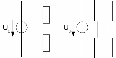
At the left picture there are two resistors in a line circuit, connected to a voltage source, at the right picture the resistors are in parallel to the voltage source. Voltage divider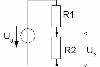
At the left picture you can see a line circuit out of two resistors connected to a total voltage U0. For the voltage at the two resistors there is: U1 + U2 = U0 and U1 : U2 = R1 : R2 The sum of the voltage across the two resistors equals the input voltage and the ratio between the voltages across the resistors equals the ratio between the values of the resistors. The input voltage is divided according to the ratio of the two resistors. That's why this kind of linear circuit is called "voltage divider". If an output voltage of 5V is needed while the input voltage is 12V, the ratio of the two resistors has to be: R1 : R2 = 7 : 5 With a resistor of 1000Ω (=1kΩ, short 1k), R1 is calculated by 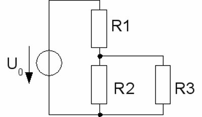
Let's connect a load to the "output" of the voltage divider. In principle we connect another resistor in parallel to R2. The circuit consists of a linear circuit of R1 and the combined resistance of R2 and R3 by now. The resistance of the R2,3 is given by:  The combined resistance of R2,3 is always lower than the resistance of R2, meaning the output voltage decreases when a load is connected to the voltage divider. The lower the value of R3 (the load), in relation to those of R2, the lower the output voltage becomes. A value of 10000Ω = 10kΩ for R3, gives a combined resistance R2,3 ≈ 909Ω. For this reason the output voltage becomes: U2,3 = U0 * R2,3/(R1 + R2,3). With R1=1.4kΩ, R2,3=909Ω and an input voltage U0=12V we get an output voltage of just 4.72V. More clearly the situation becomes with a value of just 1kΩ for the load. Hereby we get U2 ≈ 3.16V. When connecting a load to a voltage divider, the resistance of the load has to be clearly higher than those of the single divider. But lowering the resistance of the voltage divider is tricky: The resistors of the voltage divider transform electric energy to heat. Those wasted power becomes higher, the lower the total resistance of the voltage divider becomes. With R1=1.4kΩ and R2=1kΩ the wasted power is P = U02 / (R1 + R2) = 0.06W. When using R1=140Ω and R2=100Ω, to get an output voltage of 4.71V even with a 1kΩ load, the wasted power becomes 0.6W without a load connected. The electric power dissipated by the 1kΩ load is just 0.022W. That is really not an economic ratio. Electrical networksMany complex networks can be simplified step by step.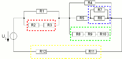
At the first step the resistors R1 + R2 (red rectangle), R8 + R9 + R10 (green rectangle), R11 + R12 (yellow rectangle) are united by simple addition. The resistance of R7 and R6 is calculated by 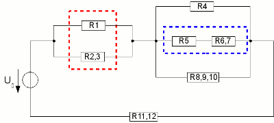
Now R1 and R2,3 are calculated by R1,2,3 = (R1 * R2,3)/(R1 + R2,3) as well as R5 and R6,7 by R5,6,7 = R5 + R6,7. We get the following network: 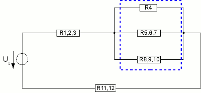
The three resistors R4 and R5,6,7 and R8,9,10 (blue rectangle) are united to a single resistor and we get the clearly arranged constellation: 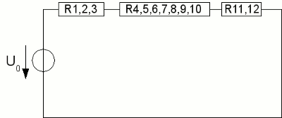
The remaining circuit consists of three resistors in series, thus the total resistance is given by simple addition. <<< Current, resistance and power Magnetism >>> News The Project Technology RoboSpatium Contribute Subject index Archives Download Responses Games Links Gadgets Contact Imprint |
|
|