|
|
|
|
News The Project Technology RoboSpatium Contribute Subject index Download Responses Games Gadgets Contact <<< AC voltage Switching operations >>> Self-inductanceWhat's first - current or magnetic field?At the chapter about magnetism we saw that a current causes a magnetic field and at the chapter induction, that an alternating magnetic field causes voltage and for this reason a current. At the chapter about eddy current we got to know Lenz's law, meaning the induced current counters the alteration of the magnetic field. Seems like a cat eats it's tail...What happens if the voltage at an inductor is altering? Linear correlation of current and voltageAt the chapter about ohmic resistance we saw that voltage and current are correlated in a linear way at those devices. If the voltage attached to an ohmic resistor changes, the current through this resistance is changing in a proportional way, too:
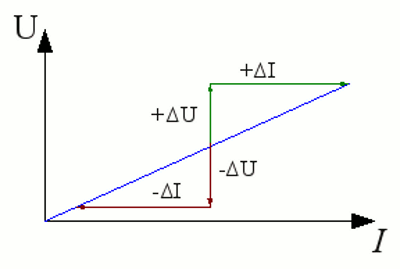
Current-voltage plot of an ohmic resistance. The result is a straight line, whose gradient corresponds to the value of the resistor (high gradient = high ohmic resistance). If the voltage attached to the resistor is lowered by -ΔU, the current decreases by -ΔI. Vice versa the current increases by +ΔI if the voltage is raised by +ΔU. It is: -ΔU / -ΔI = +ΔU / +ΔI. The resistance of a copper wire is linear (at least at the operating temperature of our electric vehicle) meaning it behaves like an ohmic resistance. If the voltage maintained along a straight copper wire is changing, the current passing through the wire changes in a proportional way. If the copper wire is wrapped around a core, a further criterion is added: The induced voltage. The induced voltage depends on the change of the magnetic flux through the area bounded by the conductor loop and it counters the change of the maintained voltage. From straight wire to a coilInduction doesn't only appear at ring shaped conductor loops, but at any closed path of conducting material. The rate of change of the magnetic flux through the conductor path is proportional to the induced voltage. To maintain voltage along a copper wire, it has to be attached to a voltage source, meaning we must build an electric circuit. As the name "electric circuit" implies, it is always a closed path of conducting material.
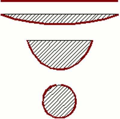
Let's have a look at the area bounded by the copper wire and the line between it's ends. At the straight wire the bounded area is zero. The wire must be bent slightly to form a small area. Finally the ring shaped wire forms an area bounded only by the wire. At the picture besides we can see that the area of the semi circle is the largest of all areas drawn. Do we get the highest induced voltage at the semi circle shaped wire at a given wire length? No! Because we can't neglect the length of the supply lines! We have to consider the length of the whole conducting loop. Here at the circle is the best shape. The relation between outline and area becomes greatest when forming a circle. InductanceIf the geometry of an inductor is fixed, the generated voltage depends only on the permeability of the environmental matter. At the chapter about hysteresis, we have seen that the permeability of ferromagnetic materials depends on the magnetic history. By now we will simplify the circumstances of the case by considering a constant value of permeability. So we get for the magnetic flux:Where is: Φ - magnetic flux, N - number of windings, L - inductance, I - current The magnetic flux is proportional to the current and inversely proportional to the number of windings. The factor is called the inductance. The symbol is L and the unit is called henry, named after the American physicist Joseph Henry. The character used is H. The inductance of one henry is given, if a voltage of one volt is induced while altering the current by one ampere per second. Together with Faraday's law of induction the generated voltage is: Where is: Φ - magnetic flux, N - number of windings, L - inductance, I - current, ε - induced voltage The induced voltage is proportional to the rate of change of the current. Attaching an inductor to a voltage source
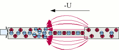
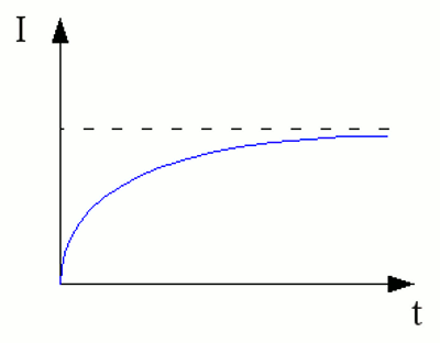
By attaching an ohmic resistor to a voltage source, an electric field is established inside of the resistor, causing a voltage with the same value but different sign as those of the voltage source. You can imagine this process by thinking of electrons being "concentrated" in front of the resistor and "evacuated" behind it. The resistor corresponds to a "bottleneck" inside of the electric circuit. As soon as an inductor is attached to a voltage source, a current starts flowing through it. The changing current induces a voltage of the same value, but different sign. The increase of current is constant over time, meaning the absolute value of current is increasing permanently. The amount of growth depends just on the external voltage and and the inductance. The current increases to infinity, because the ohmic resistance of the wire is zero. As mentioned before, inductors are mostly made of copper wires wrapped around a core. The ohmic resistance of the copper wire is different from zero and so we get the following correlation between current and time: Where is: I - current, U0 - external voltage, R - ohmic resistance of the wire, e - Euler's number, t - time, L - Inductance 
When connecting an inductor to a voltage source, the current is increasing to it's maximum value, which is related to the ohmic resistance of used wire. For the final value we get: <<< AC voltage Switching operations >>> News The Project Technology RoboSpatium Contribute Subject index Archives Download Responses Games Links Gadgets Contact Imprint |
|
|