|
|
|
|
News The Project Technology RoboSpatium Contribute Subject index Download Responses Games Gadgets Contact <<< Efficiency Power output >>> Torque curveTorque curve of an electric motorThe functionality of electric motors is based on the interaction of magnetic fields. The forces due to those fields are acting on the rotor as well as on the stator. Essential for the torque is the component pointing tangential to the rotor: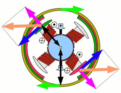
Force2 in an electric motor: Attracting forces are acting between the magnetic poles of the permanent magnets of the stator and the electromagnets of the rotor. The resulting force points into the direction of the orange vector. This force can be split into two components: One of them points tangential to the arc of rotor movement (blue arrow) the second points perpendicular to the first one (magenta colored arrow). Caused by the symmetric constuction, the compnents pointing along the axis of the rotor coil (magenta colored arrows) have the same magnitude but opposite direction. The sum of those forces is zero. The blue vectors cause a counterclockwise movement of the armature. As explained in the chapter about torque, we need to know the length of the lever and the magnitude of the (blue) force to get the resulting torque. The length of the lever (lR) is given by the radius of the rotor and the tangential force is given by (FTR). So we get: According to "action and reaction" a torque with the same magnitude but contrary direction (clockwise) is acting on the stator. There is: When recording the torque at the stator, the larger radius of the motor housing has to be considered (lR), thus in the drawing the magnitude of force acting on the stator is lower than that acting on the armature. Because of the fact that the torque acting on the stator equals those acting on the rotor (except the direction of rotation), the functionality of rotor and stator can be swapped. In a so called outrunner the stator coils form the center of the motor (=rotor at the drawing above) while the permanent magnets spin with motor housing (=stator at the drawing above). Motors of that type (sometimes called external-rotor configuration) are not commutated mechanically but use electric controllers (=brushless). Conventional configured motors are called inrunners. Torque and angle of rotation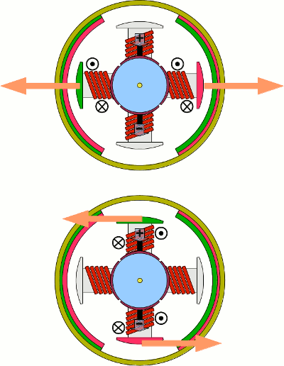
Let's have a look at the torque in relation to the angle of rotation in a conventional inrunner. Let's consider the magnetic field of the stator magnets are homogeneous to simplify the maths. For this reason the magnitude of the force acting on the rotor is constant - simply it's direction is changes with rotation. Furthermore there is no commutation of the rotor coils and just one of the electromagnets is energized. Therewith we get two special positions of the rotor: At the upper drawing the total forces point into the axis of the enabled electromagnet, consequently the resulting torque is zero. At the lower drawing the rotor is turned for 90 degrees by what the resulting forces point tangential to the rotor and the point of maximal torque is reached. 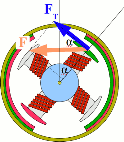
The rotational angle is called α. The angle between F and it's tangential component FT has the same magnitude. With the correlation:
For the correlation between the angle of rotation and the torque we get: Where is: M - Torque, F - force acting on the magnetic poles of the enabled electromagnet, RR - radius of the rotor, α - angle of rotation Because of the fact that F and RR are constant during rotation we get a cosine function: 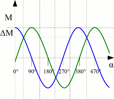
Torque in correlation to the angle of rotation: The blue plot shows the torque of the (not commutated) rotor. At α = 0° the maximum torque is reached, decreasing to zero at an angle of 90°. At the angle of 180° the highest negative value is reached. That means that the rotor is pulled contrarily to it's original direction of rotation at that point. To make the motor spinn continnuously, the polarity of the electromagnets has to be swapped by the commutator. The green plot shows the torque of the second electromagnet and is lagging for 90°. The commutator is enabling / disabling the electromagnets each 90 degrees and it is swapping the polarity each 180 degrees. To make the maximum torque act on the rotor, the switching points should be chosen in a way that the maximum torque is inside those 90 degrees, which is why the first switching point is at 45 degrees. 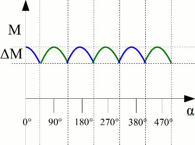
Torque curve of a commutated rotor: The drawing besides shows the torque curve of an electric motor with two permanent magnets at the stator and two electromagnets at the rotor. The commutator switches the electromagnets each 90°, by what the torque varries with ΔM. As a conclusion we can see that the average torque of an electric motor is increasing the more electromagnets the rotor has, because ΔM is lowered with a larger number of switching operations per rotation. Switching timeBesides the angle of rotation the torque of an electric motor depends on the strength of the generated magnetic fields. Until now we assumed that the magnetic field of an electromagnet is generated instantaneously as soon as it is enabled by the commutator. As treated in the chapter about switching operations, the correlation is given by [3.36]. We get a curve: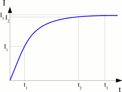
Current through an electromagnetic coil after turning on. If the electromagnetic coil is enabled by the commutator for the time span t3, the (almost) maximal current is running through it's loops and the (almost) maximal magnetic field strength is generated. The (almost) maximal torque is acting on the rotor. If the time span is shortened to t2 by increasing rotational speed, a slightly lower torque is acting, because the current through the coil is decreasing slightly. When reducing the time span to t1, the coil gets disconnected from the input voltage even though just half the maximum current is reached. Accordingly the torque decreases significantly: 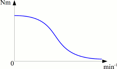
Torque in relation to revolution speed. The number of switching operations is increasing with revolution speed and the number of electromagnets at the rotor. The current running through the loops of the rotor and therefore the torque is decreasing. <<< Efficiency Power output >>> News The Project Technology RoboSpatium Contribute Subject index Archives Download Responses Games Links Gadgets Contact Imprint |
|
|