|
|
|
|
News The Project Technology RoboSpatium Contribute Subject index Download Responses Games Gadgets Contact <<< Voltage divider Multivibrator >>> Resistor-capacitor circuitThe video about RC circuitsCapacitor The simplest type of a resistor-capacitor or short RC circuit consists of one resistor and one capacitor switched in series. When connecting those circuit to a constant voltage, the voltage drop over time at the capacitor depends on the capacitance and the resistance of the circuit (see chapter switching operations for details):
[3.32]  Where is: UC - Voltage across the capacitor, UR - voltage across the resistor, U0 - input voltage, I - total current, Q - charge, C - capacitance, R - resistor, t - time, e - Euler's number 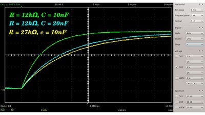
The voltage across the capacitor tends to the constant input voltage of the circuit. The higher the resistance respectively the higher the capacitance, the lower the voltage drop at the capacitor after a fixed span of time. The rate of change of the signal is maximum at the start of the charging procedure.  If the input voltage of the circuit drops to zero (e. g. the input clamps are shortened), the charged capacitor discharges it's stored energy through the resistor. An equivalent circuit consists of a charged capacitor and a resistor switched in parallel.
The voltage drop over time is as follows:  Where is: U0 - Voltage across the capacitor at t=0 C - capacitance, R - resistance, t - time, e - Euler's number The time required for the voltage to fall to [9.1] τ = R * C Where is:τ - RC time constant R - resistance C - capacitance 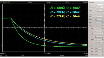
While the capacitor gets discharged, the voltage drops from the initial value down to zero. The higher the resistance respectively the higher the capacitance, the higher the voltage drop at the capacitor after a fixed time span. Once again the rate of change of the signal is maximum at the start of the procedure. Resistor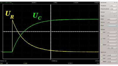
In a linear RC circuit, the voltage drop at the resistor plus those at the capacitor equals the input voltage of the linear RC circuit ( 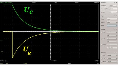
If the input voltage drops to zero, the capacitor gets discharged. Just like at the charging procedure, the current running through the circuit is highest at the start of the process (t=0). Now the voltage drop at the resistor equals those at the capacitor except the sign. The capacitor operates as the voltage source of the circuit (see equivalent circuit above). In theory, the discharging respectively charging procedure lasts for an infinite span of time, but in practise you won't be able to detect a voltage drop different from zero respectively different from the input voltage after a certain span of time. Therefore, the time required for the voltage to fall to the initial voltage divided by Euler's number is often used to characterize an RC circuit. See the definition of the RC time constant above. Square wave signal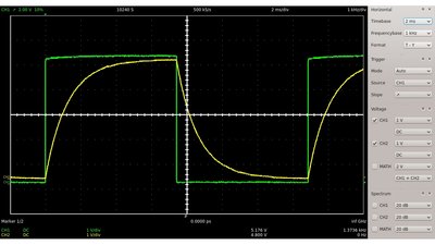
If the RC circuit is connected to a square wave signal, the capacitor gets periodically charged respectively discharged. 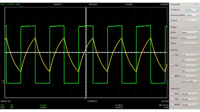
Besides the resistance and the capacitance of the circuit, the maximum voltage at the capacitor depends on the switching frequency of the input signal. The lower the frequency, the higher the peak voltage. 
With increasing switching frequency, the charge cumulated at the capacitor can't flow off respectively no additional charge can enter the device. The voltage tends to half the peak voltage of the symmetric square wave signal at the input clamps. The subsequent graphs show the signal across the resistor while the circuit is connected to the square wave signal: 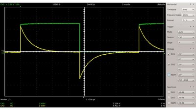
Note that the polarity of the signal alters while the capacitor gets charged respectively discharged. 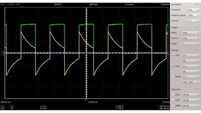
Like at the capacitor, the peak voltage across the resistor is also decreasing with increasing switching frequency. 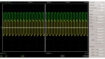
However the root mean square voltage is increasing with increasing switching frequency. The root mean square voltage is represented by the absolute area bounded by the graph and the X-axis. Sinusoidal signal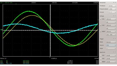
Like at the square wave signal above, the peak voltage across the capacitor decreases with increasing frequency, while those at the resistor is increasing. UInput(Green), UResistor(Blue) and UCapacitor(Yellow). 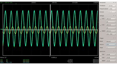
If the output is taken across the capacitor, high frequencies are rejected, while low frequencies are passed. The circuit behaves like a low-pass filter. If the output is taken across the resistor, high frequencies are passed, while low frequencies are rejected. In this configuration, the circuit behaves like a high-pass filter. The range of frequencies that passes the filter is called bandwidth. The frequency at which the signal is decreasing to Where is: f - cut off frequency R - resistance C - capacitance Besides the variation of the peak voltage, the phase angle of the output signal across the resistor in comparison to the input signal varies also with varying frequency. The resulting phase angle is given by: Where is: α - phase angle f - frequency R - resistance C - capacitance For the resulting phase angle there is: 0° < α < 90° 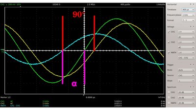
There is a phase angle of 90° between the output signals across the capacitor and the resistor of a linear RC circuit. Remember that the current through the circuit is maximum while the rate of change of the voltage drop across the capacitor is highest. F = 312.5Hz, C = 0.1μF, R = 2.7kΩ UInput(Green), UResistor(Blue) and UCapacitor(Yellow). The phase angle between input voltage and current (=voltage across the resistor) varies with the input frequency. 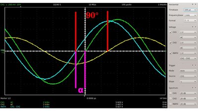
F = 1250.0Hz, C = 0.1μF, R = 2.7kΩ UInput(Green), UResistor(Blue) and UCapacitor(Yellow). The higher the frequency of the input signal, the lower the value of the phase angle between current and voltage of the input signal. Band-pass filter
If a high-pass filter is connected to the output clamps of a low-pass filter (or vice versa a low-pass to a high-pass), the whole circuit passes frequencies within a certain range and rejects frequencies outside that range. Those circuit is called band-pass filter. 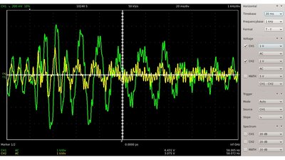
A well known use of such filters is in sound recording and reproduction. By using several filters in conjunction with amplifying circuits, the balance between frequency components within an electronic signal can be adjusted. An equalizer is used to strengthen or weaken the energy of specific frequency bands. The plot shows the input (Green) and the output (Yellow) of an audio signal passing a combined low- and high-pass filter. <<< Voltage divider Multivibrator >>> News The Project Technology RoboSpatium Contribute Subject index Archives Download Responses Games Links Gadgets Contact Imprint |
|
|