|
|
|
|
News The Project Technology RoboSpatium Contribute Subject index Download Responses Games Gadgets Contact <<< R21 cardboard My computer history >>> Feeding mobile robots with electric energyDer Film zum KapitelPower rails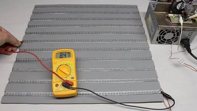
The power supply system shown here is made of a wooden base plate with metal stripes and sliding contacts. Rails with ground potential alternate with +8.5V rails. 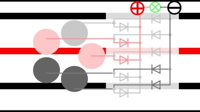
At least 5 round sliding contacts arranged on a circle and 10 diodes are needed to power the robot. If that arrangement is pulled over the base plate, at least two sliding contacts are connected to two different metal stripes at any time. With the diodes, the polarity at the input terminals of the electronic board doesn't change during movement. At the drawing, the positive terminal is always located to the left and the negative terminal to the right of the load. 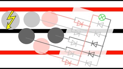
The gap between the metal stripes must be slightly larger than the diameter of the sliding contacts or else they will shorten two stripes! 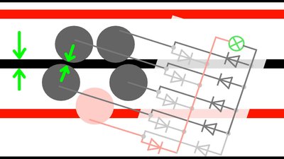
The width of the metal stripes must be larger than the gap between two sliding contacts. 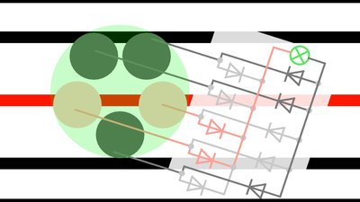
The outer diameter of the circle, the sliding contacts are arranged on, must be large enough so that three metal stripes can be touched at once. 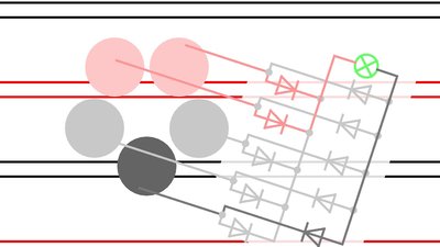
Instead of massive metal stripes, you can also use two thin cables with a distance equal to the width of the metal stripes. Less visible, but more complex to manufacture are multiple contact points that are joined at the reverse side of the base plate. 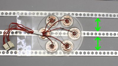
When using more than 5 sliding contacts, the gap between the metal stripes at the base plate can be enlarged. That makes the arrangement work properly even with a poorer engineering tolerance of the base plate. 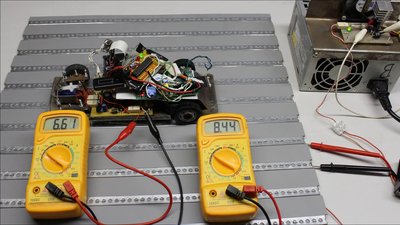
Accross the diodes and metal stripes there is a noticeable voltage drop of 1.83V, thus the voltage applied to the rails at base plate must be higher than the input voltage needed at the rover electronics. A fixed voltage regulator is needed to power the computer correctly. 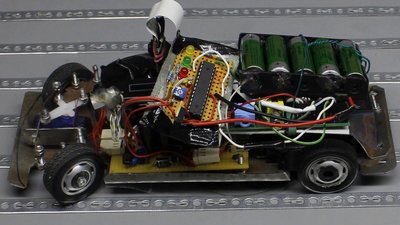
In practice there is no steady contact, because the surfaces of the metal stripes and the sliding contacts are not ideally plain and clean. A computer attached to this system will crash. Large capacitors or batteries can be used to buffer electric energy. Whenever the connection to the external power supply is interrupted, the robot is fed with electricity through the batteries, discharging these buffers. If the connection to the metal stripes is reestablished, the robot is powered through the current rail system and the batteries get recharged. A microcontroller observes the charging procedure to avoid damage of the batteries during operation. It's a very complex system, but it enables a continuos operation of the robot 24h a day and 7 days a week. Another advantage of the system is that the rover can pass gates and tunnels. <<< R21 cardboard My computer history >>> News The Project Technology RoboSpatium Contribute Subject index Archives Download Responses Games Links Gadgets Contact Imprint |
|
|