|
|
|
|
News The Project Technology RoboSpatium Contribute Subject index Download Responses Games Gadgets Contact <<< LED Matrix Switching N-channel MOSFETs >>> Basic communication through Morse codeVideo about basic data transfer between microcontrollers.OverviewIn this chapter you can read about:
Hardware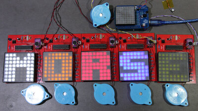
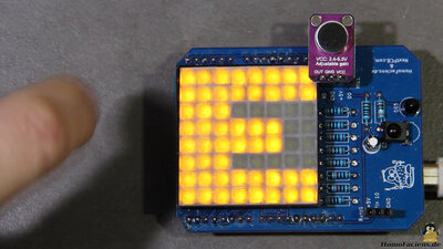
I have written example software for an Arduino UNO. The little helpers in my video are boards with an 8x8 LED matrix, the working principle of which I have shown in a previous chapter. In the video I am using acoustic signals with my hand and a mini speaker as sender. To get better visibility of the LED screens I have mounted a 3D printed grid with a sanded acrylic plastics plate on top. 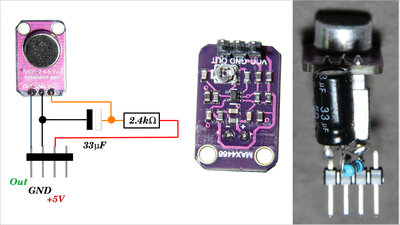
The microphone modules are type GY-MAX4466, with an adjustable gain through a potentiometer on the back side. I have mounted a low pass filter to the pin of the input voltage, composed of a 2.4kΩ resistor and a33μF elektrolytical capacitor, because the 5V pin of the Arduino UNO doesn't deliver a really smooth DC voltage. 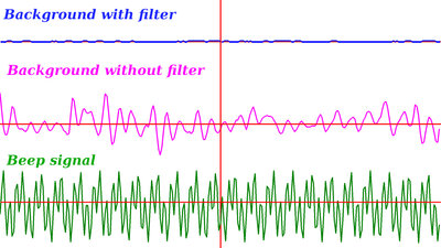
You can see the impact of the low pass filter in this drawing, that was generated on my PC from the readings of the analog to digital pin (the Perl script is part of the download package): The top curve shows background noise with the filter, the middle curve was recorded without the filter and no beep in the air and the lower curve shows a recorded beep with the filter. Counting taps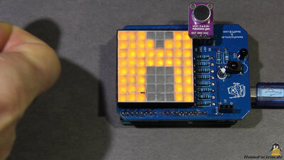
A way of transmitting data that is very easy to program makes use of counting taps. A tap is detected whenever a reading at the analog input to which the microphone is connected exceeds a certain threshold. The number of taps is counted until there is a pause of about 1.5s. That number corresponds to the position of a letter in the alphabet. The software is easy to write, but any background noise that exceeds the threshold will be misinterpreted as the transmission of a letter. Tap code
Another simple way of data transmission is the so called "tap code": 25 letters of the alphabet are listed in a table with 5 columns and 5 rows. A letter is transmitted by tapping the number of rows followed by the number of columns - there is a longer pause between the two, also after the transmission of the letter has been completed. A maximum of 10 taps is required for one letter, so more data than in the first example can be transmitted per time unit. This procedure is somewhat more stable when it comes to misinterpretation of background noise: As long as not two tap sequences with the required pause are received, the software can recognize the transmission as faulty and jumps back to the previous state. However, this method is also not totally safe against interference. Tapped Morse code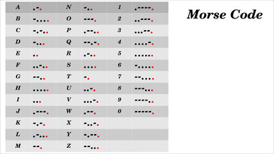
The Morse alphabet offers a way of transmitting letters with even fewer knocking signals, but this method uses more different signal states: A short and a long tone, as well as the pauses in between. Since a long tone cannot be produced when knocking, the distinction between "long" and "short" must be made using the pauses. However, following this system, for example the two letters "D" and "K" sound identically because the last knock cannot be identified as "short" or "long". A way out of this dilemma is to add a terminating tap at the end of each letter: So the "D" becomes "-..." and the "K" becomes "-.-.". The two letters can now be distinguished, same as all other letters of the alphabet, as well as the digits and some special characters. As a separator between two words, either an even longer pause can be inserted, or a special character can be transmitted, which indicates that the transmission of a word has been completed. In computer age, the "space" is used for this, although it does not appear in Morse Code, but new times require new characters - I use long, long, long, short - and don't forget the teminating knock at the end. With this modified Morse code you can transfer any text to a microcontroller quite effectively by clapping or knocking. Morse code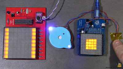
With a loudspeaker, tones can be used for data transmission, whereby the tone length can be used as an additional element for coding the characters besides to the pause length. We can therefore use the unmodified Morse alphabet - the terminating signal is no longer required, so data transmission is a bit faster. Addresses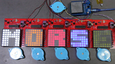
If several microcontrollers are within range, a standard must be defined with which a specific target system for the sent data can be selected. One method is to assign a unique number, i.e. an address, to each of the microcontrollers. The numbers 0 to 9 are suitable for up to 10 addresses. Each transmission now begins with the address of the target system being sent as the first character. With that, the microcontrollers can also communicate with one another. In the video I showed how letters can be swapped between different boards. 8 bit code / error detection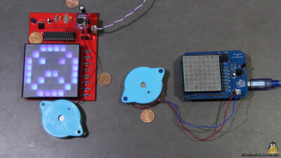
Noise can cause a transmission to run incorrectly. This means that additional commands must be inserted into the transmission standard to ensure that communication has taken place without errors. I use my own table in which all characters consist of 8 tones, which means that theoretically 256 different combinations are possible. The characters can be generated automatically with just a few lines of software code. Since 51 combinations are sufficient to transfer text and digits as well as some special characters, I only use every fifth possible combination. An error in the transmission can now be detected in two ways: On the one hand, each character must consist of 8 tones followed by a longer pause - if this is not the case, at least one tone must have been skipped or additional tones have been misinterpreted due to background noise. If 8 tones were correctly received, but a "long" was misinterpreted as "short" or vice versa, there is a chance of 4 to 5 that this combination cannot be assigned to a valid character, so that the transmission is also recognized as faulty. A special character signals to the sender that the message must be repeated, the screen shows the number of errors found. Graphics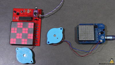
The screens of the small computer boards consist of 64 LEDs, which can represent 2 raised by the power of 64 different combinations - which is a huge number. In order to display a combination of LEDs that does not correspond to any of the stored letters, a standard must be defined that allows any graphics to be transmitted. This can be done by another special character indicating that the following signals must be assigned to a graphic. After this special character, 64 tones are transmitted, whereby a "long" corresponds to a switched on LED and a "short" to a switched off LED. The transmission takes much longer than sending a simple letter, the shape of which is stored in each of the microcontrollers. Sending graphics instead of letters is the reason why Powerpoint clowns have to transmit so much more data than people who understand to put their message into simple words and numbers. Even in the age of Gigabytes and Gigaherz, "keep it simple" is the mantra that coders must follow. Rubber wires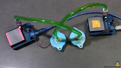
Here, I lock the sound waves in two hoses that run from the loudspeaker of one microcontroller to the microphone of the other microcontroller. This means that the sounds can hardly be heard outside - the two microcontrollers now communicate via the rubber cables. A major advantage of wired communication is that ambient noise is largely blocked - even with the simple Morse code, the transmission succeeds without errors despite external background noise. Data transmission through infrared interface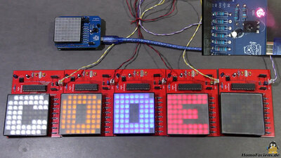
Light signals can also be used for data transmission without fiber optics - here I am using an infrared interface. The same basic rules apply to addressing the microcontroller and to coding the information - I use the Morse alphabet once more for data transmission to the 5 target systems. DownloadsThe software exaples written for the Arduino UNO are part of the download package.Sourcing partsWhen buying components via the affiliate partner links I have listed in the table (or through the banners on my pages) you help to keep my my projects going - many thanks!Clicking on the links does not mean you have to buy - you can simply browse through the pages ;-) Of course, supporting my freely accessible educational platform without shopping but by making a donation or becoming a Patreon also works. Many thanks to everyone who already sent me an obol! If you know more parts that are good for building circuits shown on this page, please leave a comment.
<<< LED Matrix Switching N-channel MOSFETs >>> News The Project Technology RoboSpatium Contribute Subject index Archives Download Responses Games Links Gadgets Contact Imprint |
|
|