|
|
|
|
News The Project Technology RoboSpatium Contribute Subject index Download Responses Games Gadgets Contact <<< Air resistance Work, energy, power >>> Experiments inside a wind tunnelFilmsThe first film illustrates the construction of the wind tunnel. The second film is about the resulting drag at different positions inside the wind tunnel. A circularly shaped plate is placed in the middle of the tunnel and at the bottom plate - quasi at the height of a car. The drag of both positions is compared. Ideally the air flow should be constant at the whole cross-section of a wind tunnel. In reality the flowing air is slowed down at the walls of the tunnel. The third film is about the drag of different shaped and arranged objects. The plate of the first experiment is compared to a hemisphere and a sphere. The fourth film is about the drag against shape, too. Here at the shape of the project car gets "optimized". The size of the car is the subject of study of the fifth film. The car manufacturers mostly just publish the CW-values of their vehicles. This value is just the half of the truth. While looking at formula [2.9] it is evident that the frontal area is included. Compact cars take a big benefit of this fact. Drag while driving in slipstream is investigated in the sixth film. The influence of the look is observed in the last film... Construction details of the wind tunnel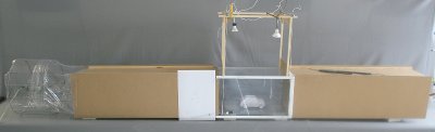
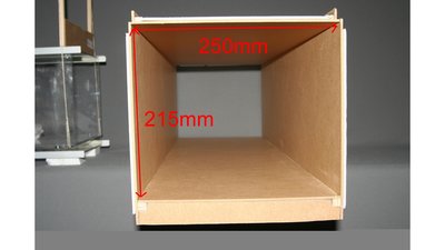
The tunnel consists of three parts. In front of the measurement platform and behind it, the air flows through two boxes being 840mm long and consisting of beaver-board. The internal dimension is 250 x 215mm. The edges are enforced by wooden strips 14 x 14mm. In principle there is: The longer the air flows before reaching the tested device, the longer is the time to fade away the turbulences, meaning the air becomes more laminar. Because of the fact that the propeller moves the air in rotation, a long tunnel behind the measuring platform is beneficial, too. 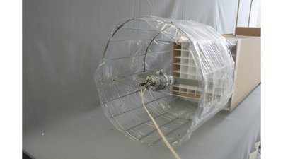
The wind is generated by an electric engine of the 700 class. A planetary gear 3.3:1 is mounted at the axle and this system rotates a propeller of the dimensions The engine is mounted at the middle of a cage soldered with 3mm wire bars. The cage is covered by wrapping film. The engine isn't blowing the air towards the tunnel, but pulls it out of the construction, because the propeller generates a lot of turbulences at his back side. 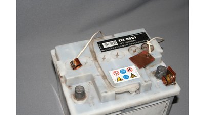
The energy source is a 12V car battery. The connection at the terminals is done by soldered copper rings. 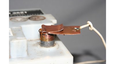
The "switch" is fixed at the positive terminal. 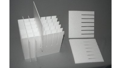
The grid at the end of the tunnel consists of 2mm Depron panels (foam). This grid prevents the air from spinning around in the direction of the propeller. One more advantage of this grid is the protective function. It avoids loosened model cars from being shredded by the propeller. 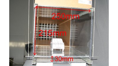
The measurement chamber consists of 4mm strong Plexiglas being enforced by aluminum profiles at the edges. Those aluminum profiles overlap 30mm to be able to insert the beaver-board boxes. The measurement platform is adjusted at the height of the bottom plate of the beaver-board boxes. An offset generates turbulences which has to be prevented. 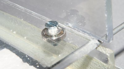
Ball bearings at the edges of the measurement platform avoid friction if the platform touches the walls of the chamber. The ball bearings are taken from two old hard disks. 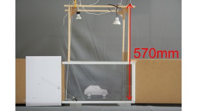
The measurement chamber is 400mm long. The measurement platform is fixed like a pendulum. The force bringing the platform back to the zero position is caused by weight. The longer the pendulum is, the more sensitive the measurement setup becomes. The wooden framework above the measurement chamber sets the pendulum length up to 570mm. 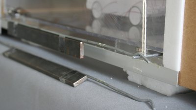
Another advantage of the pendulum is the fact that the sensitivity can be reduced by attaching additional weights. Those weights should be attached equally at both sides of the platform. 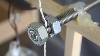
The pendulum is fixw with a loop at the bottom and by a drilled M10 thread rod at the top. Therewith the pendulum length is adjustable. 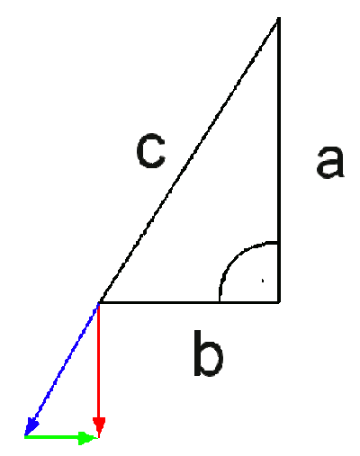
Calculating the resetting force of the pendulum: At the left picture the distance c of the upper triangle gives the pendulum length and b the elongation. Distance a can be calculated using the Pythagorean theorem: a2 + b2 = c2 or a = √(c2 - b2) At the lower triangle the red arrow gives the gravitational force (FG) and the green arrow the resetting force (FR). Both triangles are related and so there is: a / b = FG / FR or FR = b * FG / a or FR = b * FG / √(c2 - b2) The formula above demonstrates two things: 1.) With increasing elongation the resetting force is increasing, too. 2.) With increasing pendulum weight (=measurement platform + model car + additional weights) the resetting force is increasing by what the sensitivity is decreasing. 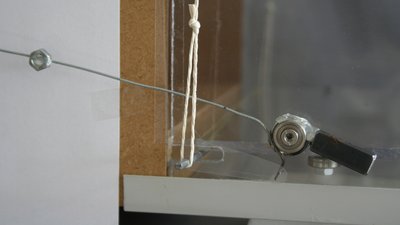
The indicator has a short lever that is connected to the plattform through a small piece of plastic (packing material). Therewith a slight movement of the plattform is turned into a turned into visible movement of the indicator needle. The linkage should be done free from clearance. The indicator axis runs through a ball bearing (from an old hard disk) and the needle is balanced by small weights. That wind tunnel can be used to demonstrate some effects concerning air resistance rather than recording values with a high precision. It is good for comparing the drag of two or more objects. List of used parts
Replica with additional features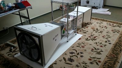
Marc built this wind tunnel to test the drag of various objects in his 8th grade class in Seattle Washington. The industrial 24 inch fan produces three speeds. The highest speed is 3,250 Cubic Feet per Minute (CFM). There is a grill that straightens the air so there is very little turbulence. 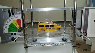
The indicator has proven to be extremely sensitive and was able to reflect very small differences in shape, size and texture of the objects. 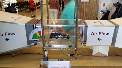
That construction was honored with an award: The project has been very well received and won 2nd place out of 64 projects - congratulations! <<< Air resistance Work, energy, power >>> News The Project Technology RoboSpatium Contribute Subject index Archives Download Responses Games Links Gadgets Contact Imprint |
|
|