|
|
|
|
News The Project Technology RoboSpatium Contribute Subject index Download Responses Games Gadgets Contact <<< Robot arm v1.0 WinchBot 1.5 >>> WinchBotThe video about WinchBotParts listMy WinchBot originates from a cooperation with RS-Components which is why links in the table point to their online shop.
Mechanics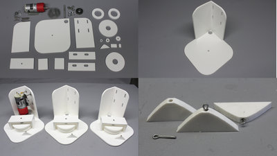
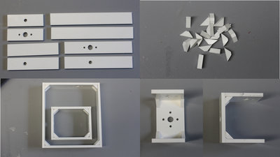
I carved all parts with my CNC v3.2 from 5mm polycarbonate plates. Use 5mm plywood if you don't have access to a CNC router, because polycarbonate is tricky to process manually. 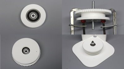
The drums have ball bearings of the dimensions 10x9x30mm Don't forget to drill a 1.5mm hole on the bottom disc (bottom left of the picture) that is used to tighten the cable. 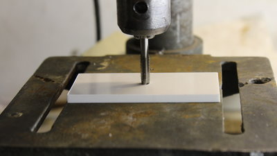
Use a tapper to cut 6mm threads in a couple of drill holes. The alignment of the taps becomes simple when using a manually operated (unplug the machine) drill press. 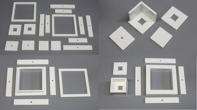
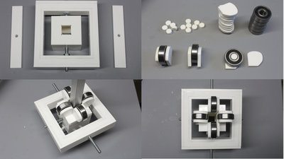
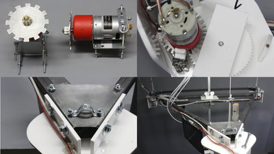
After the first test runs I have replaced the 30 teeth sensor disc by a 12 teeth version with 7mm tooth width. The distance from the center lines of the optical sensors is 10 to 11mm. A 8 teeth gear is glued to the output shaft of the motors. Instead of the gears carved with my CNC machine, you can buy module 1 gears (see parts list). 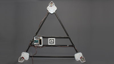
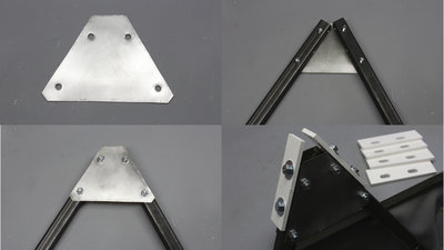
The frame is made of 20x20x1000mm steel square tubes, because I had them in stock. Use aluminum square tubes to get a lightweight frame. 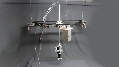
The WinchBot is hanging on three cords on the ceiling of my photo studio. Maths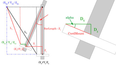
To operate the WinchBot, the X/Y/Z coordinates have to be transformed into cable lengths. Furthermore, the angle of the central square tube in the X/Z and Y/Z plain are needed to get the base frame of the servo arm aligned in parallel to the table below the bot. Figure 12 shows the Y/Z plain. To get the angle of the square tube in that plane, we need to know the distance between cord mount and pivot axis of the bearing on top (BarLength). Alpha is zero in the point of origin. If the WinchBot moves along the Y or Z axis, we get: alpha = atan(Y1 / (BarLength - Z)) Servo number 1 must compensate that rotation by turning for alpha degrees. 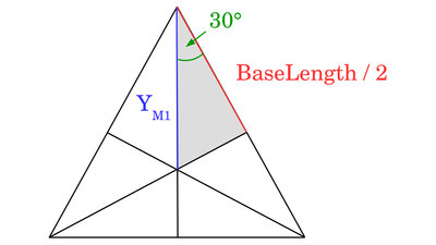
The frame of the WinchBot forms an equilateral triangle. The distance between the deviation point of Motor 1 and the center point of the triangle is needed. Equilateral triangles are also equiangular, thus we get 60° for all angles. Half that angle is 30° on top of the light grey triangle, by what we get for the distance: YM1 = cos(30°) * (BaseLength/2) ZM1 equals the length of the square tube in the point of origin (BarLength). Now we need to get the error DY and DZ caused by the fact that the cables are running to a ring with radius "CordMount" on bottom of the square tube (see figure 12). For that error we get: DY = cos(alpha) * CordMount and DZ = sin(alpha) * CordMount Finally we get the cable length at XL1/YL1/ZL1 using the Pythagorean theorem: L1 = √ ( (YM1 - Y1 - DY)2 + (ZM1 - Z1 - DZ)2 ) Electronics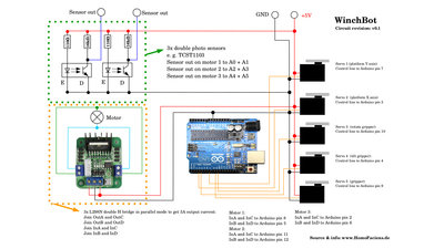
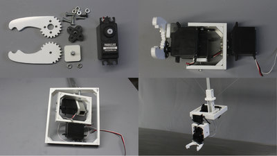
5 servos, 3 geared DC motors, 3 H bridges, 6 optical sensors and an Arduino Uno are needed to operate the WinchBot. The servos are connected through shielded cables. Connect the shield on the upper end to ground of the Arduino. Software / DownloadsThe software runs on Linux computers from the command line. You can get the package, including the installation instruction and all plans and drawings in the column Download.<<< Robot arm v1.0 WinchBot 1.5 >>> News The Project Technology RoboSpatium Contribute Subject index Archives Download Responses Games Links Gadgets Contact Imprint |
|
|