|
|
|
|
News The Project Technology RoboSpatium Contribute Subject index Download Responses Games Gadgets Contact <<< Imprint ...to be continued. >>> Next3D from GoCNCThe video about the Next3DYou can get this machine at GoCNC.de. Description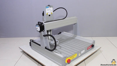
The Next3D series is available in various dimensions and as "small is beautiful" is the mantra I am preaching I have ordered version "S" which it the most compact machine offered by GoCNC. The dimensions of the mechanics are approximately 46x49x42cm at a mass of 11kg, the axes can move for 32x29.5x9cm. AssemblyThis foto series doesn't replace the build instruction of the Next3D! My pictures are meant to give you an overview of the build process and point out some changes I made.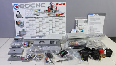
Overview of the parts and extras I got from GoCNC: The aluminum T slot plate is available as an option, same as the "G-Code Prozessor 3D" that enables you to access the Next3D through USB interface. The tools needed for the assembly are not part of the kit - building the mechanics is targeted to advanced tinkerers, skills and a tool set are basic requirements. For an extra charge you can order a fully assembled Next3D. 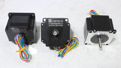
The stepper motors. 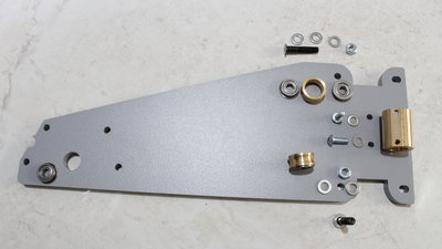
8mm steel plates give the portal design the needed torsion resistance. Brass rollers with press fitted ball bearings guide the axes. The lead nuts of the spindle drives are made of brass as well. 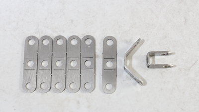
2mm steel plates are bent to U shaped fasteners. 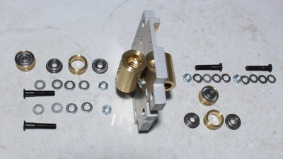
Central element of the X and Z axis. 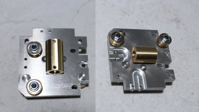
Assembled. 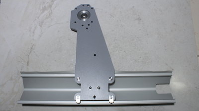
With the screws at the bottom of this foto you must apply pre-load to the rollers so that a side load of approximately 2kg is needed to move the mechanics. That's how backlash and warping of the mechanics is minimized. 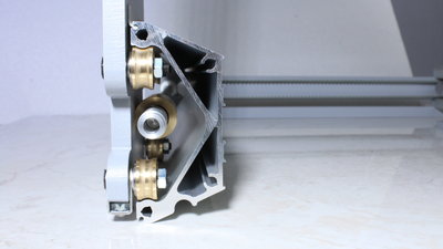
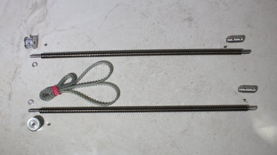
Spindels and toothed belt of the Y axis. 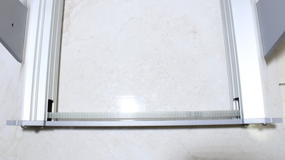
The Y axis of this portal machine is driven by just one stepper motor - the second spindle is coupled with the first one through a toothed belt. 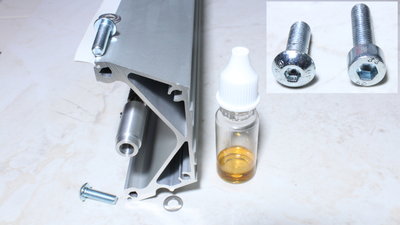
The threads on the aluminum profiles are "cut" while turning the screws in, which is why a drop of oil has to be applied to the screws beforehand. The screws with the rounded head are made for tiny hexagon tools so that they get damaged while "cutting" the threads. To avoid that, I used the more sturdy cylinder head screws to "cut" the threads before turning in the rounded head screws. 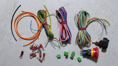
No soldering iron is needed for the wiring. 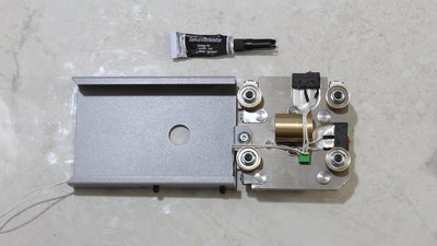
I fixed some of the the cables with drops of superglue. 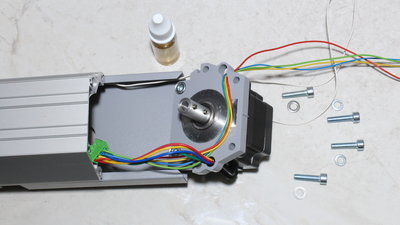
Powerful stepper motors drive all axes. 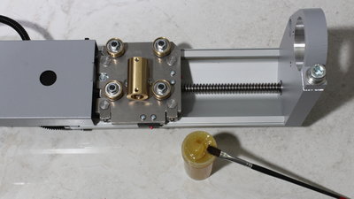
The grease that comes with the kit is for the spindles and contact surfaces of the brass rollers. 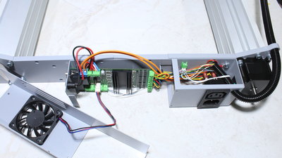
The driver board for the stepper motors is part of the kit - it has an interface for a parallel port. Nowadays computers usually don't have a parallel port, however the pin layout of the connector is part of the documentation so that you can build your own electronics if needed. 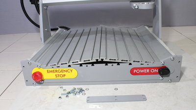
The aluminum base plate with T-slots seen here, is available as an option. 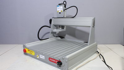
I needed two days for the build process, however I took many photos and a couple of video sequences during the assembly. You can get all pictures I have taken through my assembly as download package (61MB) Software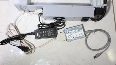
To control the Next3D through USB interface, I am using the "G-Code Processor 3D" that is available as an option. There is an Atmega328P with an Arduino Bootloader running grbl version 0.9 inside the housing. Grbl is open source so that you can flash an adopted version whenever it's needed. 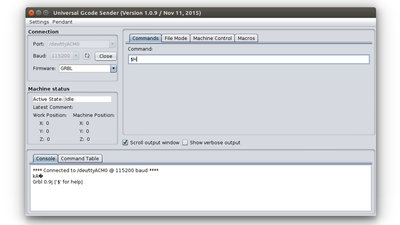
The software I am using is the Universal Gcode Sender, an Open Source program based on Java. Set the baudrate to 115200 and choose the correct port to get connected. The operating system running on my old workshop laptop is Linux Mint version 18.3. With the command "$$" you can list all parameters stored in grbl: **** Connected to /dev/ttyACM0 @ 115200 baud **** Grbl 0.9j ['$' for help] >>> $$ $0=10 (step pulse, usec) $1=25 (step idle delay, msec) $2=0 (step port invert mask:00000000) $3=2 (dir port invert mask:00000010) $4=1 (step enable invert, bool) $5=0 (limit pins invert, bool) $6=0 (probe pin invert, bool) $10=3 (status report mask:00000011) $11=1.000 (junction deviation, mm) $12=0.000 (arc tolerance, mm) $13=0 (report inches, bool) $20=0 (soft limits, bool) $21=0 (hard limits, bool) $22=1 (homing cycle, bool) $23=1 (homing dir invert mask:00000001) $24=500.000 (homing feed, mm/min) $25=500.000 (homing seek, mm/min) $26=250 (homing debounce, msec) $27=1.000 (homing pull-off, mm) $100=133.333 (x, step/mm) $101=133.333 (y, step/mm) $102=133.333 (z, step/mm) $110=4200.000 (x max rate, mm/min) $111=3000.000 (y max rate, mm/min) $112=4200.000 (z max rate, mm/min) $120=10.000 (x accel, mm/sec^2) $121=10.000 (y accel, mm/sec^2) $122=10.000 (z accel, mm/sec^2) $130=315.000 (x max travel, mm) $131=295.000 (y max travel, mm) $132=90.000 (z max travel, mm) ok Note that the direction port of the Y axis ($3=2) as well as the homing direction of the X axis ($23=1) have to be inverted. With the configuration of grbl I have chosen, the point of origin in the X/Y plane is on the front left of the machine. With the software buttons on the user interface or your keyboard you can drive the mechanics to the bottom left of your workpiece so that the router bit touches the surface. After that, press "Reset Zero". Now, you can choose a Gcode file and transfer the data by pressing the button "Send". Whenever there is a malfunction, you can stop the machine immediately by clicking on "Soft Reset" or by turning the Next3D off! <<< Imprint ...to be continued. >>> News The Project Technology RoboSpatium Contribute Subject index Archives Download Responses Games Links Gadgets Contact Imprint |
|
|