|
|
|
|
News The Project Technology RoboSpatium Contribute Subject index Download Responses Games Gadgets Contact <<< Imprint ...to be continued. >>> Longer LK5 Pro: Minimize warping by softwareThe video about fighting warpingWhen buying the Longer LK5 Pro through this affiliate link, in the onlineshop of Longer, you support my projects - thanks! Remarks on the Longer LK5 Pro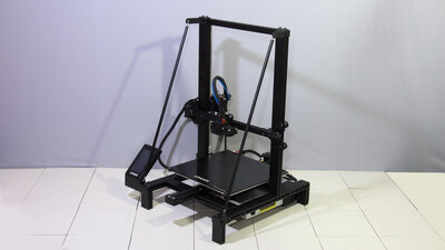
I chose the Longer LK5 Pro as experimentation platform for my ideas on the subject of "warping", because this 3D printer comes without frippery and the manufacturer publishes the source code of the firmware. Furthermore, the print volume is quite large at 30x30x40cm and large prints are particularly prone to warping. The printer is delivered mostly pre-assembled, only a few components have to be screwed on and a few cables have to be connected to one another using polarity-proof plugs. All photos that I took of the device are available as a download package (27MB). 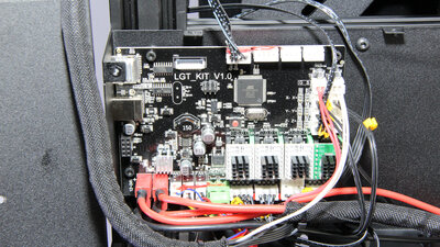
Inside a metal box in the base of the device is the mainboard with removable stepper motor drivers, which can be quickly replaced in the event of damage. The wiring looks tidy and the source code of the firmware running on the ATmega2560 is published by Longer - that's how is should be, because closed source devices no longer will enter my workshop! With the open source firmware, there are no barriers for my ideas, I have full control over the stepper motors, fans and heating elements of the 3D printer. Warping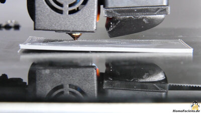
Typically, objects are printed in horizontal layers. A new strand of molten plastic is applied to a layer that has already cooled down. If the newly applied plastic also cools down, the material contracts and builds up tension along the direction of printing. With each newly printed layer, these tensions add up, all of which point in the horizontal direction. As a result, the print bends and eventually separates from the print bed at the outer ends. Not only horizontal printing: Gear rack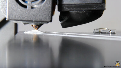
In order to direct the tensions away from the horizontal direction, I use a modified printing process: First a tetrahedron, consisting of several layers of triangles stacked on top of one another, is printed as an anchor point. 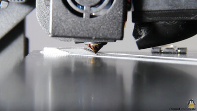
Starting from this "anchor point", the base plate of the gear rack is now printed. The printing is not done in horizontal layers: Instead, new strands of ABS are constantly being deposited on the two front surfaces of the tetrahedron. While doing so, the print head moves up and down along the Z-axis. When the tip of the tetrahedron is reached, the process starts over at the lower edge. The base plate thus grows from the rear left to the front right. For this first print the base plate is 2.15mm high and consists of 10 layers. The bottom strand is printed with a layer thickness of 0.35mm and a speed of 10mm per second. The following layers are each 0.2mm high and are printed at 30mm per second. The width of the individual strands is set to 0.6mm. The width to height ratio defines the angle of the original tetrahedron and thus the angle of the tip of the growing rack in relation to the surface of the print bed. This must be flatter than the angle of the printhead nozzle, otherwise it would touch higher layers. Care must also be taken that the print head does not touch the top layer of the base plate while the bottom line is printed. 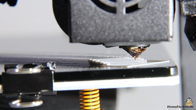
The 40cm long base plate of the gear rack shown in the video took a little more than 2 hours following this printing process. 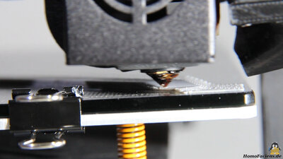
The triangular tip is filled on the left... 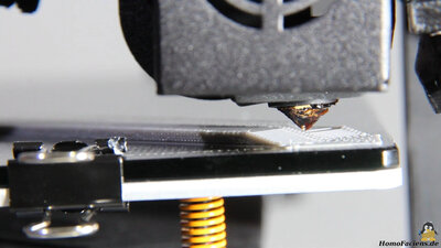
...and right side. 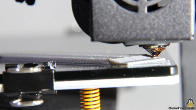
The last step is to fill in the now straightened front angle. 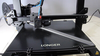
What is still missing are the teeth on top of the base plate. These are printed as usual in horizontal layers, as the angle of the teeth is too pointy to be printed using the same principle as the base plate. The teeth only extend to the center line of the base plate. 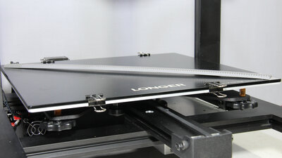
After the print has been completely detached, it can be seen that a bulge with a "hump" in the center has formed. With this printing method, too, tensions build up in the component; these are only directed in other directions. 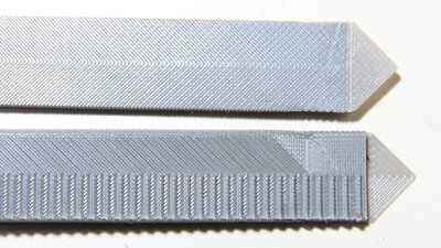
The reason why I don't print the base plate straight from bottom to top, but with a 90 degree angle, is the higher sturdiness of the finished part. 3D printed parts are stronger when forces are directed along the printed fibers and they tend to crack perpendicular to the print direction. The growth at a 90 degree angle can be clearly seen on the bottom side. The filled end of the baseplate can be seen below. 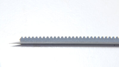
In the side view you can see that the teeth were not printed quite as precisely as intended. The reason is a bug in the Python script with which I generated the print data. Exsample print 100x50x2.15mm plate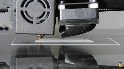
A 100x50mm plate with a height of 2.15mm is printed. A pentahedron is formed as an anchor point. This consists of rectangles stacked on top of each other. A total of 10 of these result in the required height. 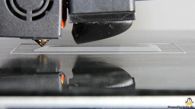
The main body now grows on all four sides. Thus, the part cooling fan must be taken into account as the lowest point of the print head. If you want to print even higher, this must be removed. 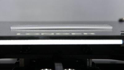
After the component has cooled down and completely detached, it can also be seen here, that the printing was by no means free of tensions. 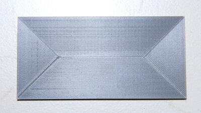
The top is printed nice and smooth. The Z-axis of the Longer is only driven from one side, but the system obviously works very well. 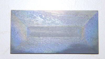
On the underside you can see that with this printing process, too, two corners (bottom in the picture) have bent very slightly upwards. The printing was carried out on the back of the glass plate, which means somewhat poorer adhesion. Example ABS box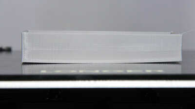
You can see that the base starts peeling off when printing 2mm thick walls on top of the plate in order to get a box made of ABS. Example "Benchy"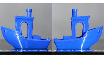
... and yeeees: of course the Longer LK5Pro can print Benchies. 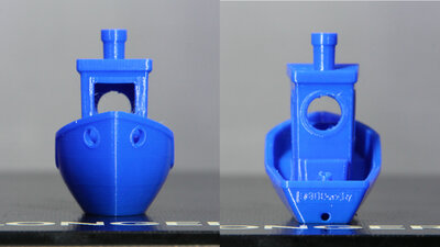
Since I'm not an expert in "benchy printing", just take a look yourself. I am happy with the result. SoftwareI generated the print data in G code format for the rack and the base plate with the help of Python scripts. The scripts, the OpenSCAD, STL and G-Code files are included in the download package.<<< Imprint ...to be continued. >>> News The Project Technology RoboSpatium Contribute Subject index Archives Download Responses Games Links Gadgets Contact Imprint |
|
|