|
|
|
|
News The Project Technology RoboSpatium Contribute Subject index Download Responses Games Gadgets Contact <<< Direct granules extruder V4 Syringe extruder >>> Direct granules extruder version 4.1The video about Extruder V4.1.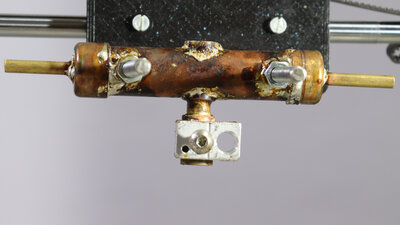
Version 4.1 doesn't look that much different than the extruder shown previously, but it's another step in the right direction. The copper pipe for the water cooling is now sealed by soldering - so water no longer drips out, even during intensive use. The extruder tube has been significantly shortened in two places: What is most noticeable is that the aluminum block with the heating cartridge is designed to be more compact, so that the hot side of the extruder could be made shorter. This not only saves weight, but the volume of heated plastic has also become significantly smaller. The larger this volume, the longer it takes for the plastic to be extruded going from solid granules at the cold end into molten state at the nozzle. Plastic decomposes at high temperatures, so it should only be heated for as short a time as possible. The second place where the tube design was reduced is the distance from the hotend to the coldend. The transition from solid to liquid takes therefore place in a smaller volume, which results in less friction on the auger screw and also a smaller force component in the direction of the nozzle. This means that the mechanics bend less during extrusion, which leads to quicker response on retract. Construction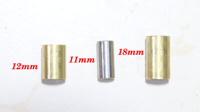
For a deeper understanding of the construction principles and for very brave early adopters, here is a rough description of how I made version 4.1: The core element is the tube and it is composed of three parts: The middle part is the heat barrier, consisting of an 11mm long piece of stainless steel tube with 6mm inner and 7mm outer diameter, which corresponds to a wall thickness of 0.5mm. On the one hand, this tube is sufficiently sturdy and, on the other hand, thin-walled enough to allow as little heat as possible to pass from the hot to the cold end. The upper and lower parts were made from 10mm round brass on my lathe - this is a cheap entry-level model that can at least machine brass with sufficient precision. 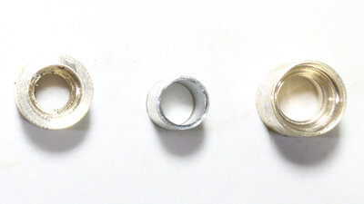
The lower part (left in the picture) is 12 to 13mm long and is first provided with a 5mm hole after it has been correctly cut to length. Then a 6mm hole with a depth of about 7mm and finally a 7mm hole with a depth of 3mm is made for the connection to the stainless steel tube. The upper part (on the right in the picture) is 17 to 18mm long. This is drilled completely through with a 6mm drill. From above, use the 7mm drill to drill approximately 8mm deep. With an 8mm drill it goes about 6mm deep and with a 9mm drill it goes about 4mm deep. At this point the granulate enters the extruder and the step bore is intended to support this process. 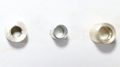
From the bottom end, an M6 thread is cut for the nozzle on the lower part (left in the picture). On the upper part there is a 7mm hole from below with a depth of 3mm for the connection to the stainless steel tube. 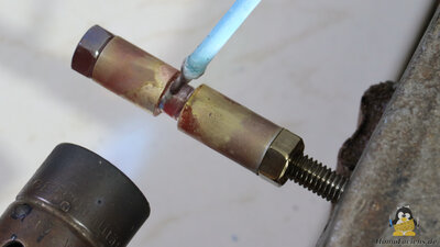
The three parts are now put on a piece of M6 thread. The parts can then be brazed with flux-coated silver solder. 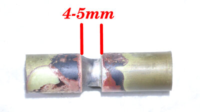
After cooling, the M6 thread can be removed for testing - the 3 parts should be joined in one line and must be air tight. 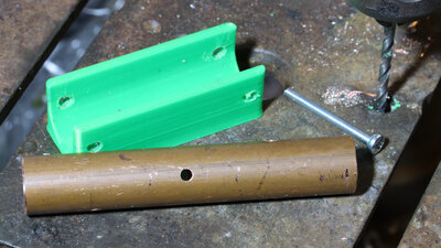
For the water cooling I use 15mm diameter copper pipe which gets the necessary holes using a 3D printed template. 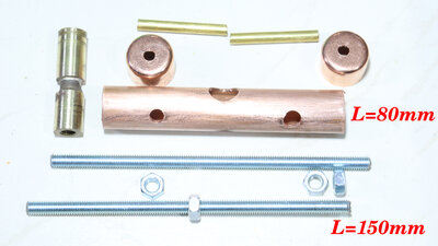
15mm Copper pipe + End caps, M5 threaded rod, 4mm brass tubes and extruder tube. 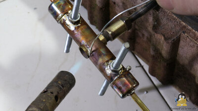
The M5 threaded rods, the end caps and the 4mm brass tubes are soldered with electronic solder - the high temperatures for brazing would weaken the copper pipe too much. Also tin solder is significantly cheaper than silver solder. If everything is air tight, the extruder tube is also connected to the copper pipe by tin solder. Make sure that the extruder tube is oriented perpendicular to the copper pipe and threaded rods. 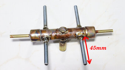
Soldered components. 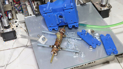
If everything is still air tight afterwards, this core component can be screwed to the plastic parts. These 3D printed parts are identical to those of the previous version. 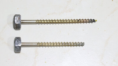
The 80mm long, 4.5mm diameter wood screw that I use for extrusion is almost identical. The only change I made was cutting off the tip. There are "saw teeth" on this, which are useful for functioning as a wood screw, but cause unnecessarily high friction when used as an auger. 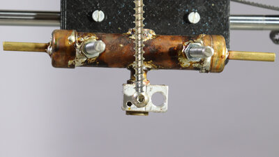
The screw extends to around 5mm above the nozzle shaft - I achieved the best results with this depth in the extruder. 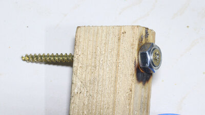
When soldering the M8 nut, a wooden block helps to center the two components. Needed partsThe printer I use is a Zonestar QR2, which to my regret is no longer manufactured.The main gear is mounted on one piece of an M8 threaded rod with two ball bearings type 608 (8x22x7mm). The hopper is attached with M3 threaded rods (4x 200mm). It is attached to the printer using M5 threaded rods (2x 200mm) A lot of M3x16 screws and M3 nuts are also required. The parts should be printed from PET-G. DownloadI created the 3D files with openSCAD. Both the scad file and the stl files are included in the download package.The track link printed as an example in the video is also available as an OBJ file for download Example print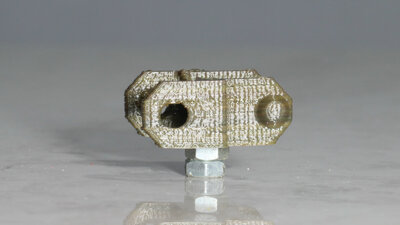
Track link: Layer height: 0.2mm Nozzle: 0.4mm Print time: 17min Size: 27x25x12mm Material: Recycled PLA <<< Direct granules extruder V4 Syringe extruder >>> News The Project Technology RoboSpatium Contribute Subject index Archives Download Responses Games Links Gadgets Contact Imprint |
|
|